


Tools Needed:
30
Please Do Not Return This Product To The Store. Contact your local Wayne-Dalton dealer.
To find your Wayne-Dalton dealer; refer to your local yellow pages / business listings or go to Find a dealer area online at www.wayne-dalton.com
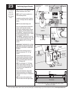
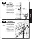
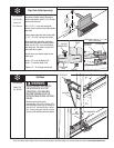
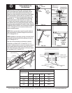
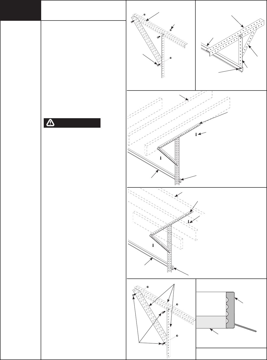
supplied). Horizontal tracks must be level
and parallel with door.
NOTE: If perforated angle is installed
over drywall, use 5/16” x 2” hex head lag
screws.
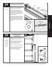
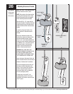
Adjust weather seal (if necessary) and
now permanently attach the weather
seal or door stop to both door jambs and
header. (They were temporarily attached
to the jambs in PREPARING THE OPENING
on page 10.) Avoid pushing weather seal
or door stop too tightly against face of
door.
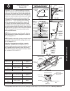
NOTE: If an idrive
®
opener will be
installed, position horizontal tracks one
hole above level when securing it to rear
supports.
Now, lift door and check it’s balance.
PRIOR TO WINDING OR MAKING
ADJUSTMENTS TO THE SPRINGS,
ENSURE YOU’RE WINDING IN THE
PROPER DIRECTION AS STATED IN
THE INSTALLATION INSTRUCTIONS.
OTHERWISE, THE SPRING FITTINGS MAY
RELEASE FROM SPRING IF NOT WOUND
IN THE PROPER DIRECTION AND COULD
RESULT IN SEVERE OR FATAL INJURY.
Adjust, if door lifts by itself (hard to pull
down) or if door is difficult to lift (easy to
pull down). Anytime spring adjustments
are made you must loosen the lock nuts
and retighten both lock nuts afterwards.
To adjust spring(s), only add or remove 1/4
turn on the counter at a time. Adjust both
sides equally.
IMPORTANT: DO NOT ADD OR REMOVE
MORE THAN 1 SPRING TURN FROM
SPECIFIED AMOUNT. IF THE DOOR STILL
DOES NOT OPERATE EASILY, LOWER
THE DOOR INTO THE CLOSED POSITION,
UNWIND SPRING(S) TO ZERO, AND
RECHECK THE FOLLOWING ITEMS:
1.) Check the door for level.
2.) Check the TorqueMaster
®
spring tube
and flagangles for level and plumb.
3.) Check the distance between the
flagangles - must be door width
plus 3-3/8” to 3-1/2”.
4.) Check the counterbalance cables
for equal tension - adjust if
necessary.
5.) Rewind the spring(s).
6.) Make sure door isn’t rubbing on
jambs.
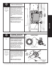
NOTE: As a safety feature, the right hand
end bracket cannot be disassembled
for service until the spring is completely
unwound and the counter cover reads
zero.
After door installation is completed, refer
to the idrive
®
owner’s manual.
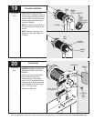
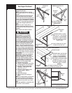
Rear Support Continued...
PERFORATED
ANGLE
ANGLE BOLTED TO CEILING
MEMBER AND PARALLEL TO
DOOR
HORIZONTAL
TRACK
ANGLE
(3) 5/16”
NUTS
(3) 5/16”
BOLTS
BOLT MUST EXTEND INTO
THE TRACK TO SERVE AS
A ROLLER STOP
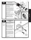
VERTICAL
ANGLE
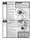
PERFORATED ANGLE
(3) 5/16” BOLTS
& NUTS
HORIZONTAL
TRACK
BOLT MUST EXTEND INTO THE TRACK
TO SERVE AS A ROLLER STOP
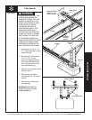
PERFORATED
ANGLE
PERFORATED ANGLE - BOLTED
USING (2) 5/16” X 1-5/8” HEX HEAD
LAG SCREWS TO CEILING MEMBER
AND PARALLEL TO WIDTH OF DOOR.
SPACE LAG SCREWS NO FURTHER
THAN 24” APART.
SOUND FRAMING MEMBERS
SOUND FRAMING MEMBERS
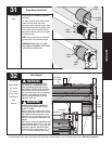
HORIZONTAL
TRACK
BOLT MUST EXTEND INTO THE TRACK
TO SERVE AS A ROLLER STOP
JAMB
WEATHER
SEAL
PERMANENTLY ATTACHED
WEATHER SEAL
PERFORATED ANGLE
PERFORATED ANGLE -BOLTED USING
(2) 5/16” X 1-5/8” HEX HEAD LAG
SCREWS TO CEILING MEMBERS
AND PARALLEL TO WIDTH OF DOOR.
ATTACH VERTICAL PERFORATED ANGLE
BETWEEN THE (2) 5/16” X 1-5/8”
HEX HEAD LAG SCREWS, SECURING
PERFORATED ANGLE TO CEILING
MEMBERS.
WARNING