


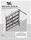

9
Please Do Not Return This Product To The Store. Contact your local Wayne-Dalton dealer. To find your local Wayne-Dalton dealer, refer to your
local yellow pages/business listings or go to the Find a Dealer section online at www.wayne-dalton.com
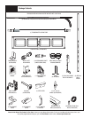
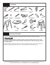
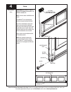
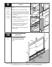
Tools Needed:
Tools Needed:
INSTALLATION
3
Power Drill
7/16” Socket
Driver
Torx Bit
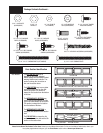
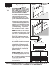
NOTE: For door section identification see
page 4.
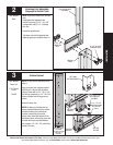
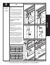
Align the center hole of bottom bracket
with hole #3 in the end stile of bottom
section. Fasten with (2) 1/4”-20 x 11/16”
self drilling screws and (1) 1/4”-20 x 5/8”
tamper-resistant self drilling screw as
shown.
Repeat for other side.
NOTE: All doors are provided with the
tamper resistant fastener for the bottom
brackets. However, the professional
installer is most likely to have the
proper tool to install this fastener. If the
homeowner does not have the proper tool
to install the tamper resistant fastener,
use a regular 1/4 – 20 x 7/8” self drilling
screw in its place.
Bottom Bracket
1
2
3
4
5
6
7
LEFT HAND
BOTTOM BRACKET
BOTTOM
BRACKET
(2) 1/4”-20 X 11/16”
SELF DRILLING
SCREWS
(1) 1/4”- 20 X 5/8”
TAMPER-RESISTANT
SELF DRILLING
SCREW
BOTTOM
BRACKET
BOTTOM
SECTION
WARNING
LABEL
END STILE HOLE
PATTERN
(LEFT SIDE IS SHOWN.
RIGHT SIDE IS
OPPOSITE.)
#3 HOLE
CENTER HOLE
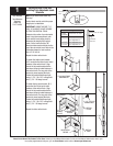
2
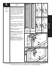
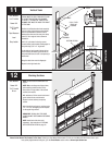
NOTE: If you have riveted track, skip this
step.
Hand tighten the flagangle to the
vertical track using (2) 1/4”- 20 x 5/8”
carriage bolts and (2) 1/4”- 20 flange
hex nuts.
Repeat for opposite side.
The flange nuts will be tightened after
flagangle spacing is complete (Step 14).
None
Attaching Fully Adjustable
Flagangle to Vertical Track
(2) 1/4”- 20
FLANGE HEX
NUTS
FULLY ADJUSTABLE
FLAGANGLE
(2) 1/4”- 20 X 5/8”
CARRIAGE BOLTS
VERTICAL
TRACK