


11
Please Do Not Return This Product To The Store. Contact your local Wayne-Dalton dealer. To find your local Wayne-Dalton dealer, refer to your
local yellow pages/business listings or go to the Find a Dealer section online at www.wayne-dalton.com
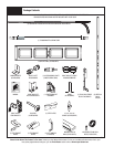
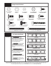
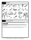
Tools Needed:
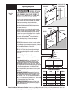
INSTALLATION
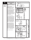
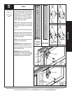
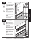
Position the lower (numbered) leaf of the
#1 end hinge over the #1 and #4 holes in
the top of the end stiles, and secure to the
end stiles by 1/4”-14 x 5/8” self tapping
screws. Position and secure #1 center
hinge(s) with 1/4”-14 x 5/8” self tapping
screws using the pre-punched holes in
the top of the center stile(s).
NOTE: The #1 hinges serve as end hinges
on the bottom section. The #1 hinges also
serve as center hinges at all center hinge
locations.
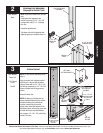
Insert roller into appropriate hinge tubes.
Repeat for all other sections using the #2
end hinges on the second (lock section)
and the #3 end hinges on the third section
(intermediate section).
NOTE: #4 End hinges are used on fourth
section of five section doors.
IMPORTANT: WHEN PLACING ROLLERS
INTO END HINGES #2 AND HIGHER, THE
ROLLER GOES INTO THE TUBE FURTHEST
AWAY FROM SECTION.
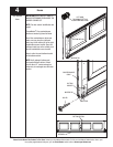
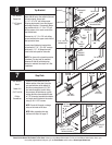
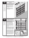
IMPORTANT: ONCE FASTENER ARE
SNUG AGAINST HINGE LEAF, TIGHTEN AN
ADDITIONAL 1/4 TO 1/2 TURN TO RECEIVE
MAXIMUM DESIGN HOLDING POWER.
Hinges
END STILE HOLE
PATTERN
(LEFT SIDE IS SHOWN.
RIGHT SIDE IS
OPPOSITE.)
7
6
5
4
3
2
1
#1 HINGE #2 END HINGE
#3 END HINGE
#4 END HINGE
CENTER STILE
HOLE PATTERN
ROLLER
PLACEMENT
ROLLER
PLACEMENT
ROLLER
PLACEMENT
HINGE
(2) 1/4”-14 X 5/8”
SELF TAPPING
SCREWS
CENTER STILE
(2) 1/4”-14 X 5/8”
SELF TAPPING
SCREWS
HINGE
END STILE
END HINGE PLACEMENT
CENTER HINGE PLACEMENT
#4 HOLE
#1 HOLE
Power Drill
7/16” Socket
Driver
5