


27
Please Do Not Return This Product To The Store. Contact your local Wayne-Dalton dealer. To find your local Wayne-Dalton dealer, refer to your
local yellow pages/business listings or go to the Find a Dealer section online at www.wayne-dalton.com
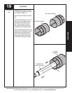
Tools Needed:
INSTALLATION
27
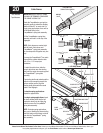
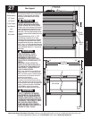
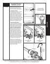
Rear Support
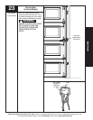
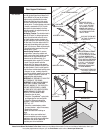
Raise the door until the top section and
half of the next section are in a horizontal
position. Do not raise door any further
since rear of horizontal track is not yet
supported.
RAISING DOOR FURTHER CAN
RESULT IN DOOR FALLING AND
CAUSE SEVERE OR FATAL INJURY.
Clamp a pair of vice clamps on the vertical
tracks just above the second roller on one
side, just below the second roller on the
other side. This will prevent the door from
raising or lowering while installing the rear
support.
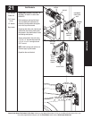
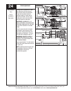
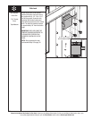
Using perforated angle, 5/16” x 1-5/8”
hex head lag screws and 5/16” bolts
with nuts (may not be supplied), fabricate
rear support for horizontal tracks. Attach
horizontal tracks to the rear supports with
5/16”-18 x 1-1/4” hex bolts and nuts (may
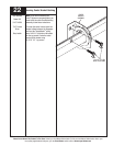
not be supplied). Horizontal tracks must be
level and parallel within 3/4” maximum of
door edge.
KEEP HORIZONTAL TRACK
PARALLEL AND WITHIN 3/4”
MAXIMUM OF DOOR EDGE,
OTHERWISE DOOR COULD FALL,
RESULTING IN SEVERE INJURY OR
DEATH.
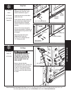
IMPORTANT: DO NOT SUPPORT THE
WEIGHT OF THE DOOR ON ANY PART OF
THE HORIZONTAL TRACK HANGER THAT
CANTILEVERS 4” OR MORE BEYOND A
SOUND FRAMING MEMBER.
NOTE: If rear supports are to be installed over
drywall, use 5/16” x 2” hex head lag screws.
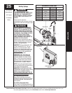
NOTE: If an
idrive
®
opener is installed, position
horizontal tracks one hole above level when
securing it to rear supports.
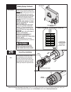
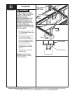
NOTE: Perforated ceiling angle must be
attached to sound framing members with lag
screws. Nails should not be used. Permanently
attach the weather seal to both door jambs and
header. (Temporarily attached in PREPARING
THE OPENING on page 6.) Avoid pushing
weather seal too tightly against face of door.
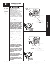
PRIOR TO WINDING OR MAKING
ADJUSTMENTS TO THE SPRINGS,
ENSURE YOU’RE WINDING IN THE
PROPER DIRECTION AS STATED IN
THE INSTALLATION INSTRUCTIONS.
OTHERWISE, THE SPRING FITTINGS
MAY RELEASE FROM SPRING
IF NOT WOUND IN THE PROPER
DIRECTION AND COULD RESULT IN
SEVERE OR FATAL INJURY.
WARNING
WARNING
Ratchet Wrench
1/2” Socket
1/2” Wrench
(2) Vice Clamps
Tape Measure
Level
Hammer
Step Ladder
DOOR IN THE
UP POSITION
VERTICAL
TRACK
VICE
CLAMPS
TOP SECTION
3/4”
Door Edges
3/4”
Horizontal Tracks
Horizontal
Tracks
WARNING