


VIVOTEK
User's Manual - 7
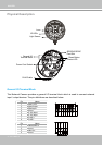
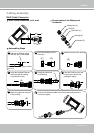
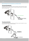
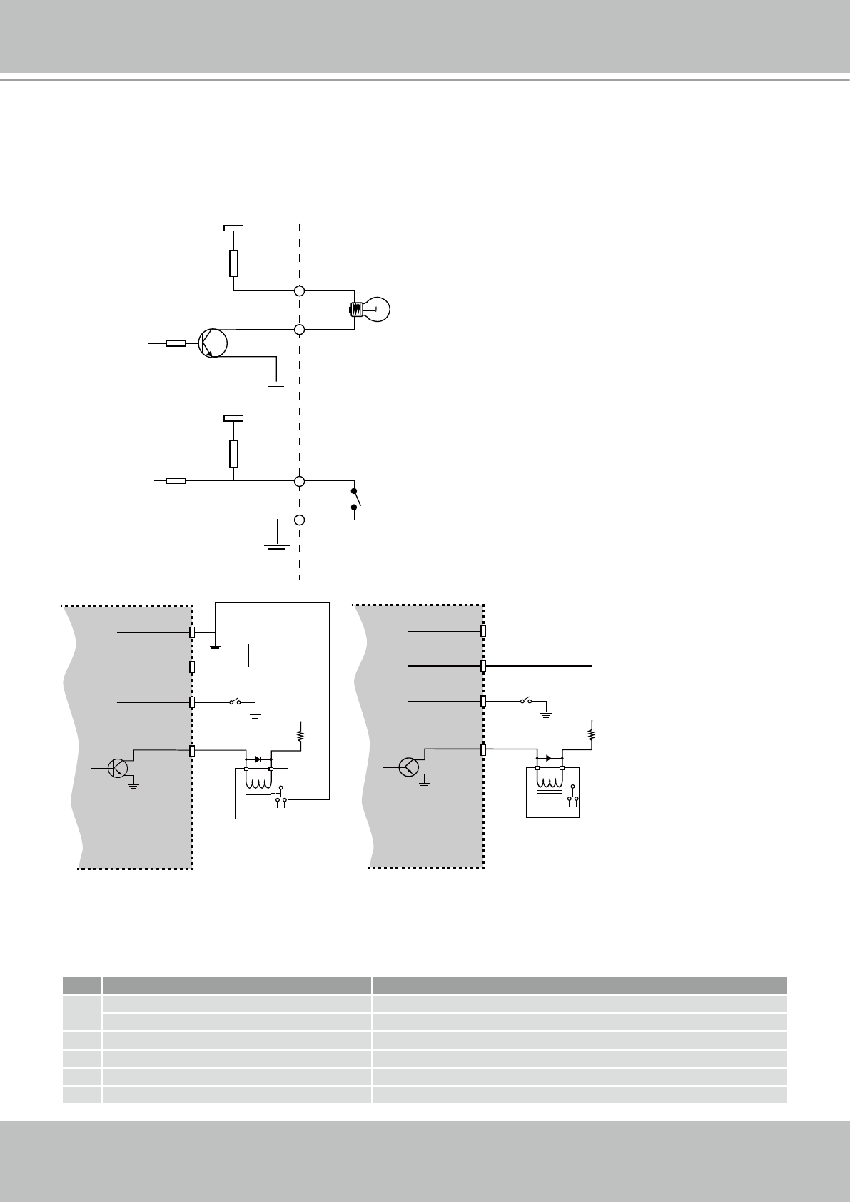
DI/DO Diagram
Please refer to the following illustration for the connection method.
12V
+12V
Digital output
PIN 1
Power+12V
PIN 2
Digital input
PIN 3
Ground
PIN 4
Gnd
Camera Power
Input
Output
4
1
3
2
+30
VDC
Max.
VDC
Switch
Relay
BJT transistor
Gnd
Camera Power
Input
Output
4
1
3
2
+12
VDC
VDC
Switch
Relay
BJT transistor
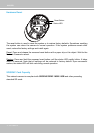
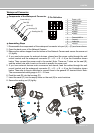
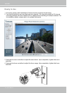
Status LED
The LED indicates the status of the Network Camera.
Item LED status Description
1
Steady Red Power on and system booting
Red LED Off Power off or power is supplied but the network is disconnected.
2 Steady Red Network works (heartbeat)
3 Red Blinks every 2 sec. Audio mute (heartbeat)
4 Blink Red every 0.15 sec. Upgrading Firmware
5 Blink Red every 0.15 sec. Restoring default