UH-PRC002-EN54
Dimension and
Weights
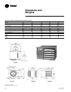
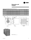
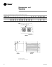
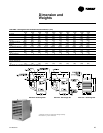
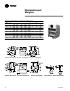
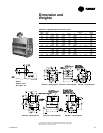
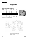
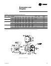
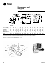
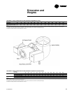
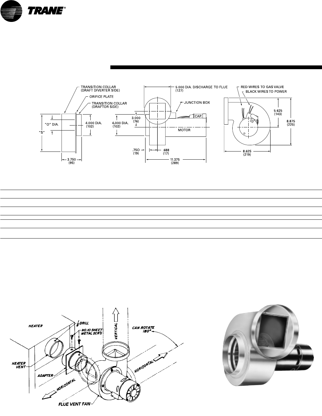
Table DW-14 – Flue Vent Dimensional Data (Field Installed)
Unit Size Input MBh 30 45 60 75 100 125 150 175 200 225 250 300 350 400
(kW) (8.8) (13.2) (17.6) (22.0) (29.3) (36.6) (43.9) (51.2) (58.6) (65.9) (73.2) (87.8) (102.5) (117.1)
Heater To Ventor Draftor 1-¼ 1-¼ 1-¾ 1-¾ 2-
1/8
2-
15/16
2-½ 33-¼ 3-½ 3-¾ 444
Orifice Size “0” (32) (32) (44) (44) (54) (75) (64) (76) (83) (89) (95) (102) (102) (102)
Normal 4 4 5 5 6 6 7 7 8 8 8 10 10 12
Flue Size “S” (102) (102) (127) (127) (152) (152) (178) (178) (203) (203) (203) (254) (254) (305)
Type: R-round, Ov-oval R R R R R R R R R R R OV OV OV
Recommended Flue 3 4 4 4 4 4 4 4 5 5 5 5 5 6
Pipe Diameter (76) (102) (102) (102) (102) (102) (102) (102) (127) (127) (127) (127) (127) (152)
Maximum Length Of Run 100 100 100 100 100 100 100 100 100 100 100 100 100 100
ft. (m) (30.5) (30.5) (30.5) (30.5) (30.5) (30.5) (30.5) (30.5) (30.5) (30.5) (30.5) (30.5) (30.5) (30.5)
Notes:
1. Installer may choose to use five-inch where four-inch pipe is shown
2. Runs should be reduced as follows for listed accessories. Each 90° elbow-10 feet. Each 45° elbow-5 feet. Briedert cap or equivalent-10 feet.
3. Discharge of the flue vent fan is five inches. Therefore, a transition by the installer is required on 30 through 175 MBh and 400 MBh units.
On units 30-250 MBh, flue vent fan and adapter ship in the same box. On units over 250 MBh, flue vent fan and adapter ship in separate boxes.
Motors are
1
/12
th
hp. 115V fans draw 2.2 amps. 208 and 230V fans draw 1.1 amps.
Transition


