UH-PRC002-EN16
Selection
Procedure
Determine the total heating load
requirements in accordance with
methods recommended by the ASHRAE
Handbook of Fundamentals or other
acceptable means.
Propeller Fan Unit Heater
1
From the performance data tables, select
the unit whose heating output meets or
exceeds the heating load requirement.
2
Airflow (cfm) and temperature rise can
be read directly from the performance
data tables.
3
Knowing the mounting height of the
unit, throw can be determined from the
performance data table. If the throw is
not adequate, consider using a larger
propeller fan unit heater or a centrifugal
fan unit heater with an optional
discharge nozzle for greater throw.
Selection Example —A natural gas
propeller fan unit heater that can provide
75 MBh heating output is required. The
unit will be mounted 10 feet above the
floor and a 40-foot throw is required.
Select the unit as follows:
a
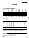
From Table PD-5, select a GPND-010 with
a 100.0 MBh input and 80.0 MBh heating
output, 1,480 cfm and a 50°F
temperature rise.
b
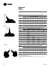
From Table GD-2, throw at a mounting
height of 10 feet is 54 feet.
Centrifugal Fan Unit Heater
1
From the performance data tables, select
the unit whose heating output meets or
exceeds the heating load requirement.
2
Airflow (cfm) ranges are listed for each
unit size in the performance data tables.
Knowing either the desired airflow or
temperature rise, the other can be
calculated using the following formulas:
cfm =
Output x 1,000
1.085 x ∆T
∆T =
Output x 1,000
1.085 x cfm
3
Knowing the mounting height of the
unit, throw can be determined from the
performance data table. If the throw is
not adequate, a discharge nozzle can be
used to obtain additional throw.
Selection Example —An LP (Propane)
gas centrifugal fan unit heater that can
provide 150 MBh heating output is
required. An airflow of 2,000 cfm is
desired. The unit will be mounted 12 feet
above the floor and a 65-foot throw is
required.
Select the unit as follows:
a
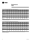
From Table PD-7, select a GCPD-020 with
a 200.0 MBh input and 160.0 MBh
heating output. An airflow of 2,000 cfm
is within the allowable range, and
temperature rise is calculated as follows:
∆T =
MBh x 1,000
1.085 x cfm
∆T =
160 x 1,000
= 74.0°F
1.085 x 2,000
b
From Table GD-2, throw at a 12-foot
mounting height is 61 feet. As a 61-foot
throw is not adequate, a 60 degree
nozzle can be selected (from Table
GD-4) which provides a throw of
76 feet.
Duct Furnace
1
From the performance data tables, select
the unit whose heating output meets or
exceeds the heating load requirement.
2
Given the airflow to be supplied to the
duct furnace, temperature rise and
pressure drop through the duct furnace
can be read directly from the
performance data charts. If the air
temperature rise is below 30°F, some
supply air must be bypassed around the
duct furnace. If the air temperature rise is
over 80°F, additional supply air must be
delivered to the duct furnace.
Selection Example — A natural gas duct
furnace that can provide 300 MBh
heating output is required. An airflow of
5,000 cfm is being provided to the duct
furnace.
Select the unit as follows:
a
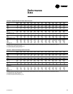
From Table PD-8, select a GDND-040 with
a 400.0 MBh input and 320.0 MBh
heating output.
b
From Chart PD-1, temperature rise at
5,000 cfm is 58°F and pressure drop is
0.16 inches.
Horizontal Blower Assembly
1
From the performance data tables, select
the blower assembly that provides the
needed airflow at the required static
pressure, and determine the required
motor size and fan speed.
2
If a blower assembly is to be used with a
duct furnace, refer to the dimensional
data table to determine which blower to
use with the given duct furnace. The duct
furnace pressure drop must be added to
the pressure drop of the duct system
before entering the blower assembly
performance data tables. Enter the
performance data table at the required
airflow and at the total external static
pressure to determine the motor size
and fan speed.
Selection Example — A GDND-040 duct
furnace is to be used with a horizontal
blower assembly. An airflow of 5,000
cfm is required. The pressure drop of the
duct system is 0.54 inches, and the
pressure drop of the duct furnace is 0.16
inches.
Select the unit as follows:
a
From Table DW-13, select a HBAC-45 for
use with the GDND-040 duct furnace.
b
From Table PD-9, an HBAC-45 at 5,000
cfm and 0.7 inches static pressure (0.54
inch ductwork + 0.16-inch furnace)
requires a 1½ hp motor with a fan speed
of 720 rpm.


