


94
2
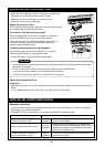
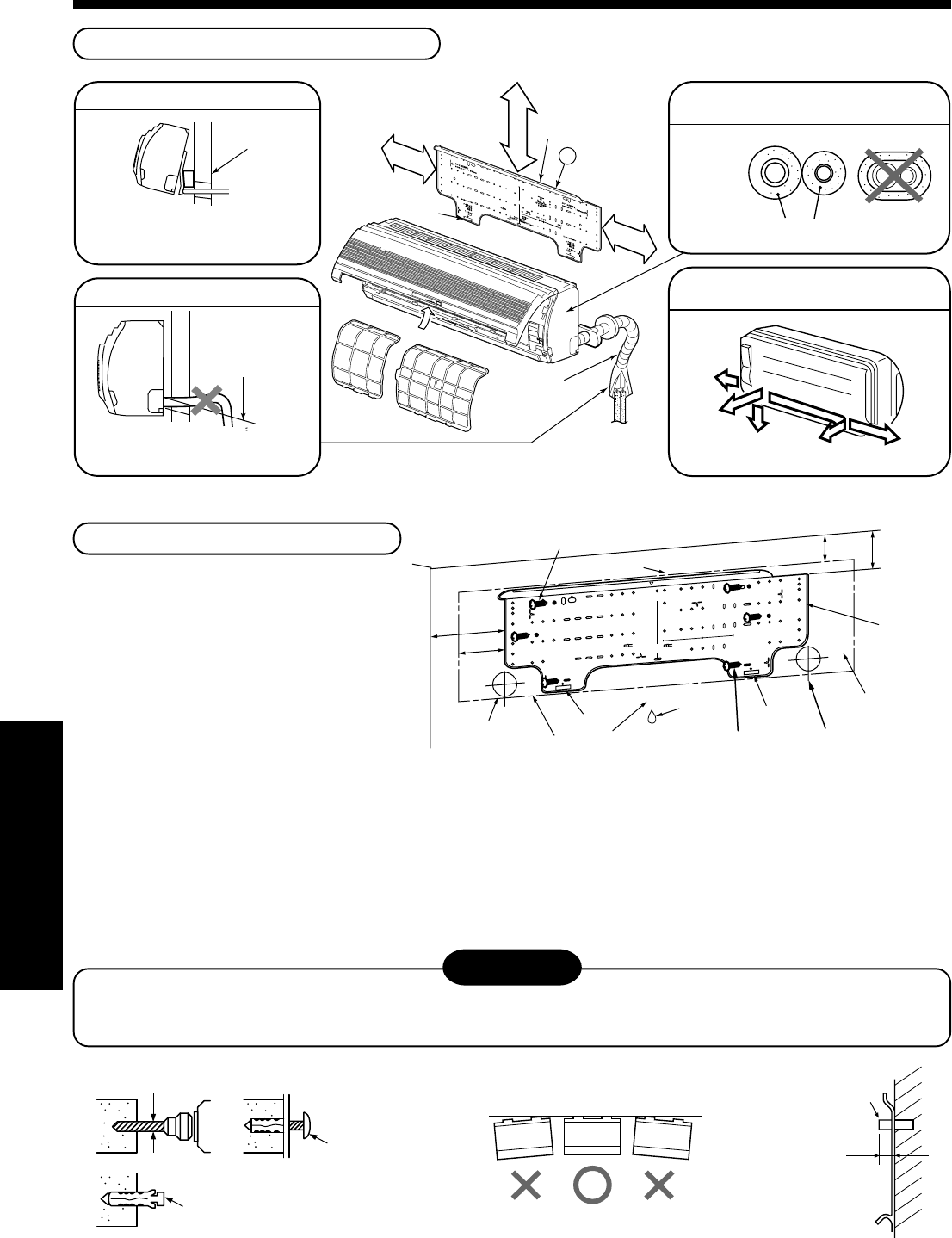
INSTALLATION PROCEDURE
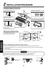
Installation Diagram of Indoor Unit
Air filter
Min. 6 mm thick heat resisting polyethylene foam
Bottom
Right
Rear left
Rear
Left
Cut the piping hole
sloped slightly
Wall
For rear left and side pipe exit
Do not allow the drain hose to sag.
Make sure to run the drain hose
sloped downward.
The auxiliary piping can be connected
the left, rear left, rear, right or bottom.
Insulate the refrigerant pipes
separately with insulation, not together.
Insert the cushion between the
indoor unit and wall, and lift indoor
unit to make work easier.
Hook
1 Installation
plate
Hook
170mm
or more
65mm or more
170mm
or more
Pipe
insulation
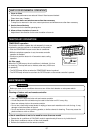
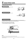
Mounting the Installation Plate
For installation of the indoor unit,
use the paper template included.
When the installation plate is directly mounted on the wall
1. Securely fix the installation plate to the wall by screwing it through the upper and lower fixing holes.
2. To mount the installation plate on a concrete wall with anchor bolts, utilize the anchor bolt holes as illustrated in
the above figure.
3. Attach the installation plate horizontally to the wall.
CAUTION
When installing the installation plate with mounting screw, do not use the anchor bolt hole.
Otherwise the unit may fall down and result in personal injury and property damage.
Ø5mm hole
Clip anchor
(local parts)
Mounting screw
Ø4 x 25mm
Anchor bolt
Projection
15mm or less
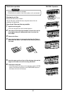
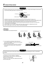
Indoor unit
Weight
Installation
plate
Pipe holeMounting screw
Mounting screw
Pipe hole
Thread
Hook
Hook
Hook
0
8
0
1
00
1
00
m
m
1
00
m
m
1
80
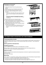
Indoor unit
55
65
170
120
RAV-SM560KRT-E
RAV-SM800KRT-E