


78
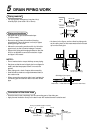
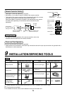
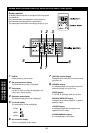
Cabling diagram
• For details of cabling/installation of the remote controller, refer to the
Installation Manual attached to the remote controller.
9
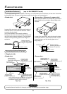
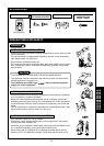
INSTALLATION/SERVICING TOOLS
Tools
¡
: Newly prepared (They are special requirements for R407C, separate from those for R22.)
o : Existing tools are available.
For the details of the tools, refer to the Installation manual of the outdoor unit.
Tools
Gauge manifold
Charge hose
Electronic balance for
refrigerant charging
Torque wrench
(nominal diam.
1/4, 3/8, 1/2, 5/8)
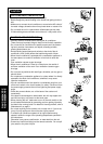
Tools
Flare tool (clutch type)
Gauge for projection
adjustment
Vacuum pump adapter
Gas leak detector
Applicable to R22 model
o
o
¡
o
Applicable to R22 model
¡
__ ____
¡
o
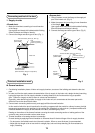
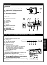
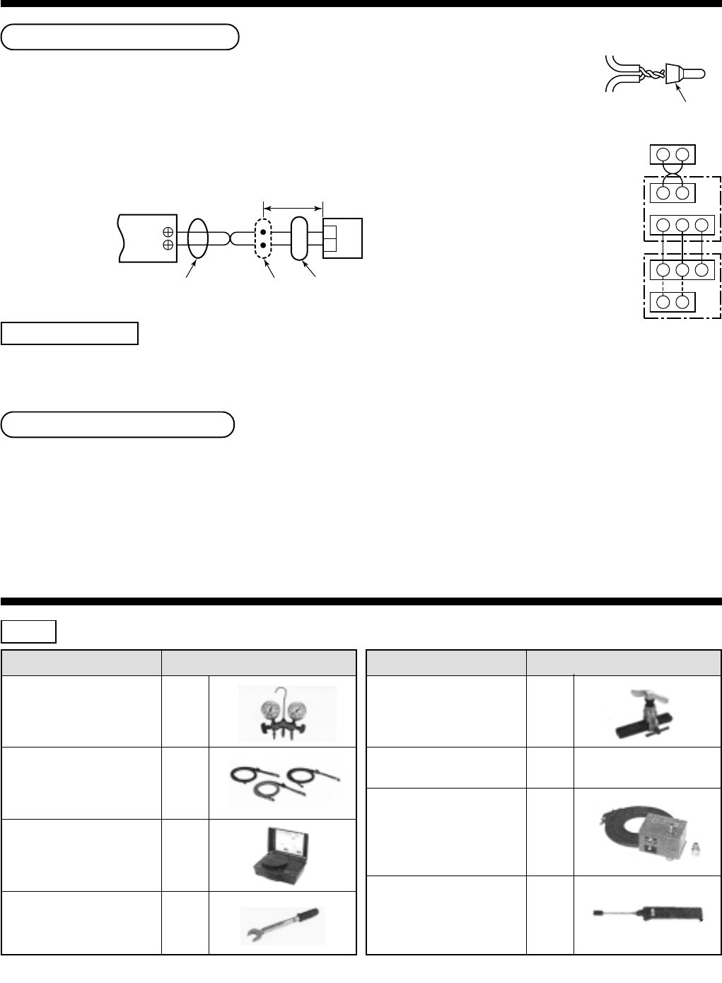
Remote Controller Cabling
• Strip approx. 14mm the cable to be connected.
• Non polarity, 2 core cable is used for cabling of the remote controller.
• Twist cable of the remote controller to be connected with cable of the remote
controller unit (or sensor), and press-fit them with a wire joint.
(Wire joints (White: 2 pieces) are included in the attachments to the remote
controller (sold separately) or the wireless remote controller kit (sold
separately).
Cable from remote
controller unit
Remote controller cabling
Wire joint
Terminal block
for remote controller
cabling of indoor unit
A
B
Approx. 200mm
W : White
B : Black
W
B
Remote controller cable
(Procured locally)
Remote controller unit or
cable from sensor part
Connecting
part
Remote controller
unit or sensor part
A B
1 2 3
1 2 3
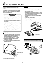
L N
Remote controller
Remote controller
cable
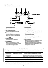
Indoor side
Outdoor side
(Single phase 220/230/240V)
Indoor/Outdoor
connecting cable
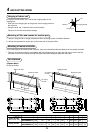
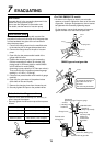
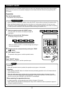
Check and Test Operation
Be sure to test the pipe connections for gas leak.
• Check the flare nut connections, valve stem cap connections and service port cap connections for gas leak with a
leak detector or some soap water.