


103
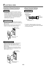
Installation of Remote Controllers
Precautions
1. Low-voltage circuit provision is used for remote
controller communication, and as such, the remote
controller cable is subject to the low-power circuit
provision of internal wiring regulations and therefore
it cannot be brought into direct contact with a high-
voltage AC power line, or housed in the same
conduit tube as a power line.
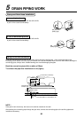
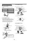
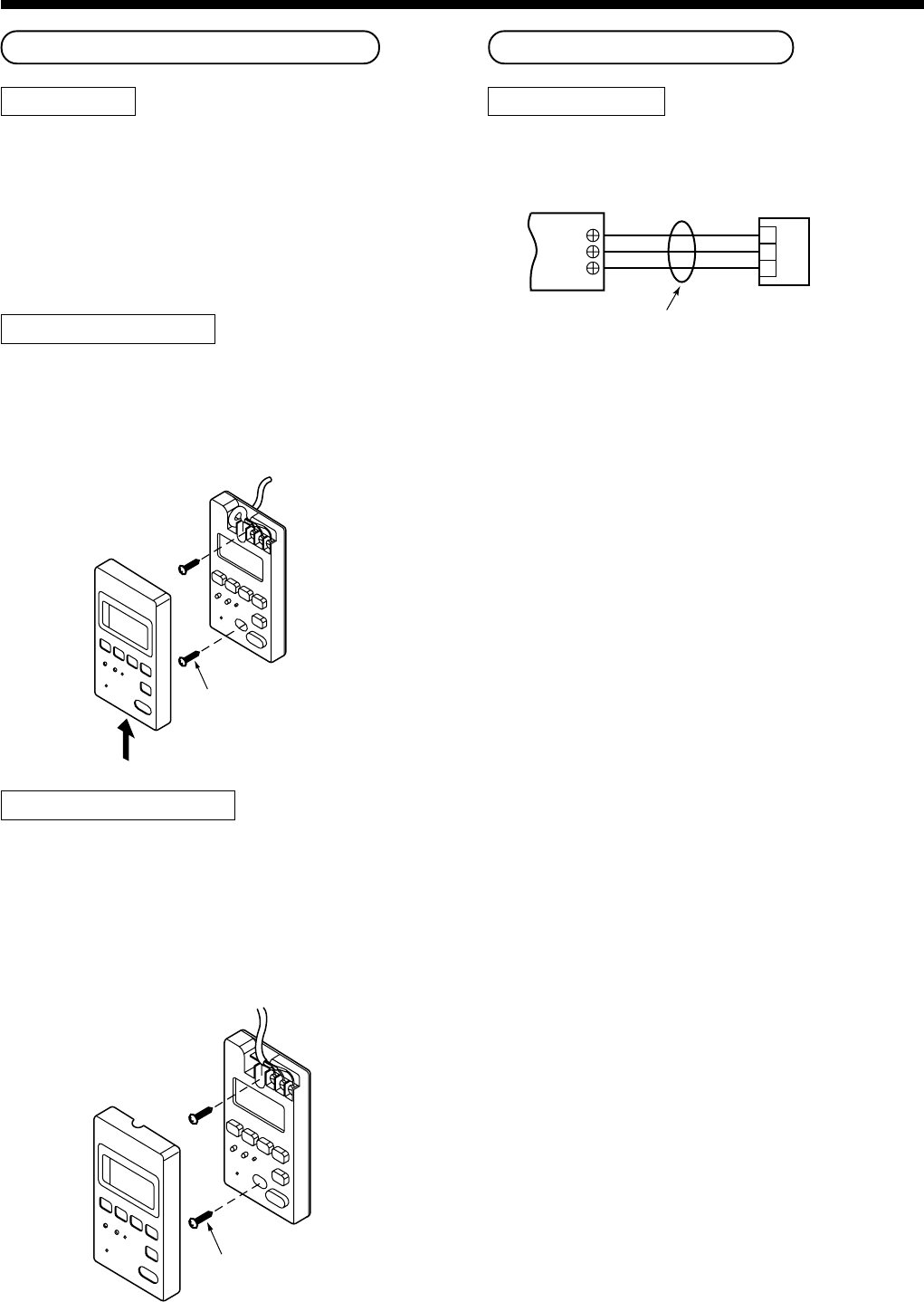
Flush wall mounting
• Feed the 3-core cable (obtained locally) though the
back of the remote controller and then connect to the
ABC terminals.
• Attach the remote controller to the wall using two
suitable mounting screws (obtained locally).
Wall surface mounting
• Attach the remote controller to the wall using two
suitable mounting screws (obtained locally).
• Connect the 3-core cable (obtained locally) to the
ABC terminals.
• Make a U-shaped cut-out in the center of the top
edge of the decorative cover and pass the 3-core
cable though the cut-out.
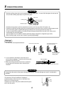
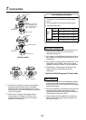
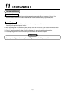
Remote Controller Cabling
Cabling diagram
• For details of cabling/installation of the remote
controller, refer to the Installation Manual packaged
in the remote controller.
Terminal block
for remote controller
cabling of indoor unit
A
B
C
A
B
C
Remote controller cable
(Local procure)
Remote
controller unit
or sensor part
3-core cable,
obtained locally
Mounting screws (x 2)
obtained locally
3-core cable,
obtained locally
Mounting screws (x 2)
obtained locally
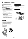
8
ELECTRICAL WORK