


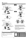
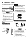
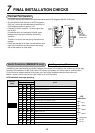

18
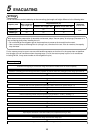
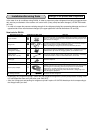
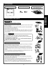
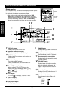
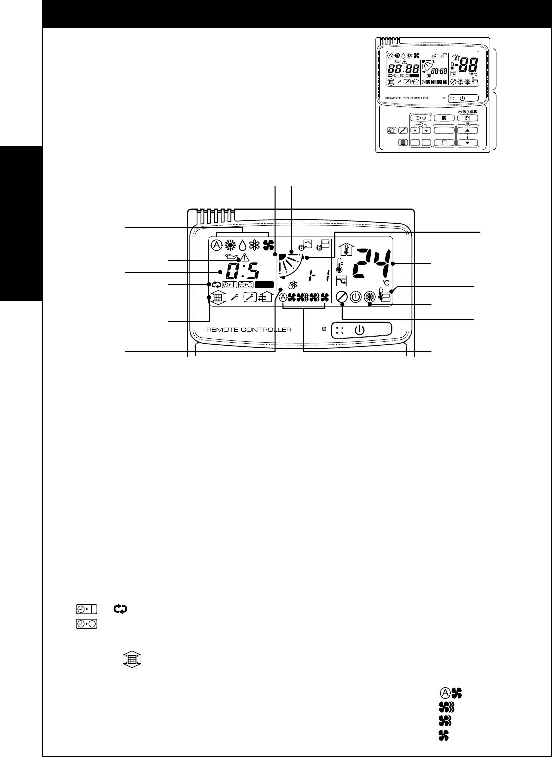
PARTS NAME OF REMOTE CONTROLLER
Display section
In the display example, all indicators are displayed for the explana-
tion.
In reality only, the selected contents are indicated.
• When turning on the leak breaker at the first time, [SET
DATA] flashes on the display part of the remote controller.
While this display is flashing, the model is being automatically
confirmed. Accordingly, wait for a while after [SET DATA]
display has disappeared, and then use the remote controller.
1
SET DATA display
Displayed during setup of the timer.
2
Operation mode select display
The selected operation mode is displayed.
3
CHECK display
Displayed while the protective device works or a
trouble occurs.
4
Timer time display
Time of the timer is displayed.
(When a trouble occurs, the check code is dis-
played.)
5
Timer SETIN setup display
When pushing the Timer SETIN button, the
display of the timer is selected in order of [OFF]
→ [OFF] repeat OFF timer → [ON]
→ No display.
6
Filter display
If “FILTER ” is displayed, clean the air filter.
7
TEST run display
Displayed during a test run.
8
Flap position display
Displays flap position.
9
SWING display
Displayed during up/down movement of
the flap.
10
Set up temperature display
The selected set up temp. is displayed.
11
Remote controller sensor display
Displayed while the sensor of the remote
controller is used.
12
PRE-HEAT display
Displayed when the heating operation
starts or defrost operation is carried out.
While this indication is displayed, the
indoor fan stops or the mode enters in
LOW.
13
No function display
Displayed if there is no function even if
the button is pushed.
14
Air volume select display
The selected air volume mode is dis-
played.
(AUTO)
(HIGH)
(MED.)
(LOW)
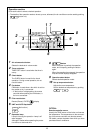
Display
section
Operation
section
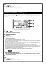
UNIT
SET
CL
SETTING
UNIT No.
CODE No.
TEST
SET DATA
R.C. No.
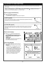
SETTING
UNIT No.
CODE No.
TEST
SET DATA
R.C. No.
1
2
8
9
10
11
12
13
14
5
6
7
3
4
RAV-SM560UT-E
RAV-SM800UT-E