


46
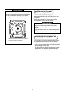
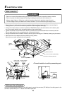
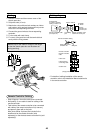
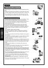
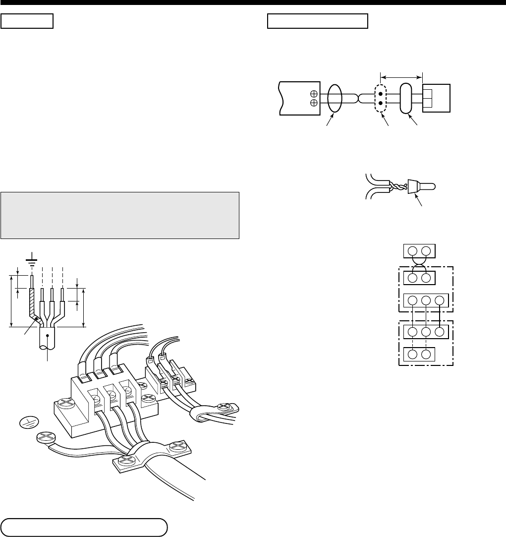
Cabling
1. Remove a screw and then remove cover of the
electric parts box.
2. Strip wire ends (10 mm).
3. Match wire colors with terminal numbers on indoor
and outdoor units’ terminal blocks and firmly screw
wires to the corresponding terminals.
4. Connect the ground wires to the corresponding
terminals.
5. Fix the cable with cord clamp.
6. Fix cover of the parts box and the terminal block
surely with the fixing screws.
Make a loop on the cable for margin of the length
so that the electric parts box can be taken out
during servicing.
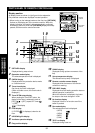
Terminal block
for remote controller
cabling of indoor unit
A
B
Approx. 200mm
W : White
B : Black
W
B
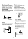
Remote controller cable
(Local procure)
Remote controller unit or
cable from sensor part
Connecting
part
Remote
controller unit
or sensor part
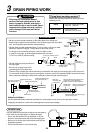
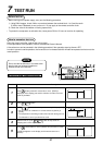
Remote Controller Cabling
• Strip off approx. 14mm the cable to be connected.
• Non polarity, 2 core cable is used for cabling of the
remote controller.
• Twist cable of the remote controller to be connected
with cable of the remote controller unit (or sensor),
and press-fit them with a wire joint.
Wire joints (White: 2 pieces) are included in the
attachments to the remote controller (sold
separately) or the wireless remote controller kit (sold
separately).
Cable from remote
controller unit
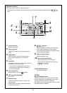
Remote controller cabling
Wire joint
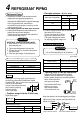
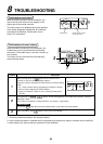
A B
1 2 3
1 2 3
L N
Remote controller
Remote controller
cable
Indoor side
Outdoor side
(Single phase 220/230/240V)
Indoor/Outdoor
connecting cable
Cabling diagram
• For details of cabling/installation of the remote
controller, refer to the Installation Manual attached to
in the remote controller.
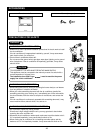
Connecting
cable
Earth line
10
30
10
40
123