


36
35˚
434.5
80
240
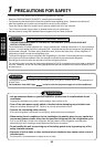
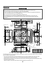
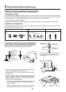
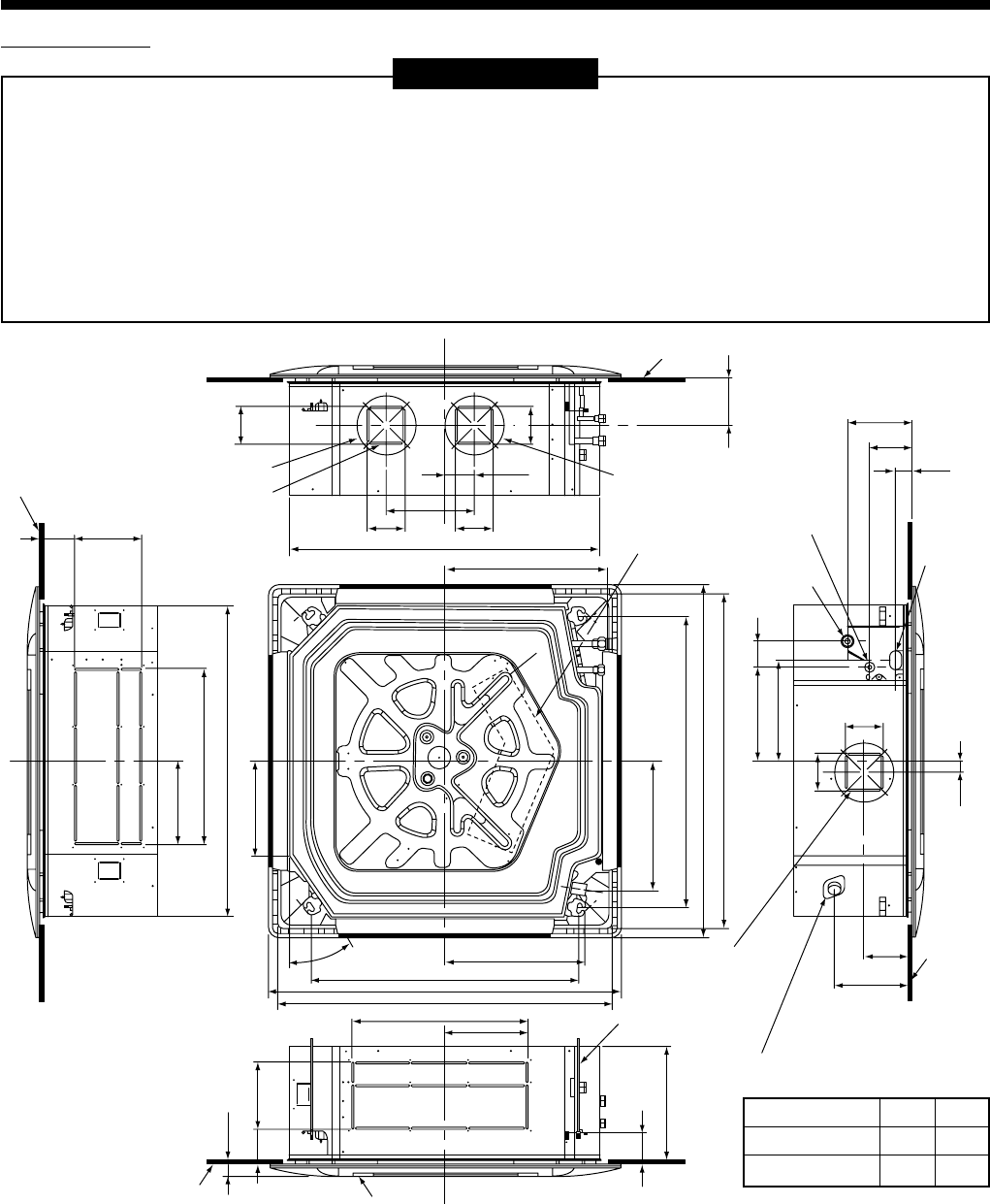
840 Unit external dimension
Ceiling bottom surface
Ceiling bottom surface
Hanging bolt
M10 or Ø3/8
(To be procured locally)
Refrigerant pipe
connecting port
A
Take-in port
of pipes
Refrigerant pipe
connecting port
B
105 105
381.6
345.5
254.5
790 Hanging bolt pitch
950 Panel external dimension
860 to 910 Ceiling opening dimension
480
723 Hanging bolt pitch
Ceiling bottom
surface
Ceiling panel (sold separately)
950 Panel external dimension
860 to 910 Ceiling opening dimension
Electric parts box
227
256
88
12097
35
227
480
840 Unit external dimension
12097
105
105
Ø162
Ø162
130
105
250
270
70
30
173
113
45
105
130
210
Ceiling
bottom
surface
Knockout square
hole for divide duct
For Ø150
(2 positions)
Knockout square hole
for divide duct
For Ø150
Drain pipe connecting port
External view
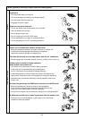
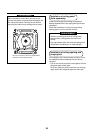
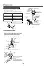
REQUIREMENT
Strictly comply with the following rules to prevent damage of the indoor units and human injury.
• Do not put a heavy article on the indoor unit. (Even units are packaged)
• Carry in the indoor unit as it is packaged if possible. If carrying in the indoor unit unpacked by necessity, be
sure to use buffering cloth, etc. to not damage the unit.
• To move the indoor unit, hold the hooking metals (4 positions) only.
Do not apply force to the other parts (refrigerant pipe, drain pan, foamed parts, or resin parts, etc.).
• Carry the package by two or more persons, and do not bundle it with PP band at positions other than
specified.
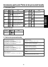
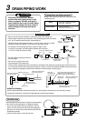
RAV-SM560UT-E
RAV-SM800UT-E
AB
Ø6.4 Ø12.7
Ø9.5 Ø15.9
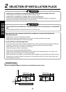
Considering pipe/wire connecting work inside the ceiling after the indoor unit has been hanged, select an installation
place and determine piping direction.
• If the ceiling has already been set before hanging the main unit, prepare refrigerant pipe, drain pipe, indoor
connecting wire, remote controller cord, etc. up to the place where pipe and wire can be connected.
• Check the size of the indoor unit, and match the indoor unit size, with ceiling opening size and that position using
the attached installation pattern.
(Attach the pattern to the lower side of indoor unit with attached four screws M5 x 16L.)