


21
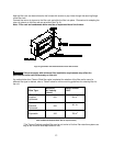
M. BLOWER CONTROLLER INFORMATION FOR ECM MOTOR
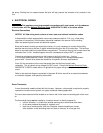
TERMINAL DEFINITIONS & FIELD WIRING
Burner Harness Connector P1
Pin 1- Limit switch connector.
Pin 2- 120 VAC Line connection.
Pin 3- Burner pilot contact.
Pin 4&5- 120 VAC Neutral connections.
Pin 6- Burner pilot contact.
Pin 7&8- From oil primary control.
Pin 9- Limit Switch Input (LSI).
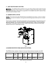
Field Wiring to Burner
Harness Wires
Riello Connections
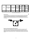
Thermostat / Humidistat connections
“C” Common / ground
“W” Thermostat call for heat
“R” 24 VAC to thermostat
“G” Thermostat call for fan
“Y” Thermostat call for cool
“DEHUM” Humidistat call for dehumidification (TXV systems ONLY)
Male quick connect terminals.
“S1-3” 120 VAC Hot
“N1-7” 120 VAC Neutral
“EAC” Electronic Air Cleaner (120 VAC) connection
“FAN” Fan On Signal
“X” 24 VAC from transformer
“C” 24 VAC common from transformer
“CC” Compressor Contactor
“CC_COM” Compressor Contactor Common
“LOW” Continuous Blower Speed
“HEAT” Blower heat speed tap
“COOL” Blower cool speed tap
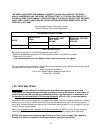
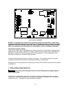
Inputs
Power supplies
Line voltage is applied between the “S1” and “N1” quick connect terminals. 24 VAC Class II
Transformer secondary voltage supplied to X and C
Limit switch
The 120 VAC optically isolated limit switch input is connected on pin P2-1 & 9. Refer to the Heat
Mode section for the control operation.
Thermostat call for heat “W”
24 VAC thermostat input. A call for heat is recognized when the thermostat connects “W” to “R”. This
input has an indicator LED that will light when the control receives a call for heat. Refer to the Heat
Mode section for the control operation.
Pilot (Tstat) Neutral Line
Yellow Wires
White
Red
T-stat terminals
White
Black