


16
If available, the use of ultra-low or low sulfur (less than 0.0015% S and 0.05% S, by weight,
respectively), no. 2 fuel oil is highly recommended. Low sulfur fuel oil can help to significantly reduce
instances of blockage and corrosion of the oil burner fuel delivery system (especially the nozzle), the
furnace heat exchanger, and the flue gas venting system. Air pollutants emitted by the furnace and the
typical malodorous smell of oil combustion will be reduced.
1. The use of black steel pipe and malleable iron fittings or heavy wall copper is recommended for
all fuel oil service lines. Never use galvanized steel piping or fittings for any fuel oil lines.
2. Where practical, provide rigid supports for the piping.
3. If the piping size in a run must be reduced, use reducing couplings only. Avoid the use of
reducing bushings.
4. Remove all pipe thread burrs and inspect the pipe for dirt or other foreign material prior to
connecting. If present, remove any deposits in the piping and discard any excessively corroded
piping.
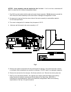
5. A readily accessible, design-certified, manual oil shutoff valve, with a non-displaceable rotor
member, shall be installed in the fuel oil supply piping within 6 feet of the appliance.
6. A pipe union, or flanged connection, shall be provided downstream from the manual oil shutoff
valve to permit removal of the appliance oil pump. Pipe unions must be the ground joint type or
flanged-jointed using a gasket resistant to the corrosive action of fuel oils.
7. Pipe dope or thread sealant design-certified to be resistant to the action of fuel oils should be
used on all threaded joints. Thread sealant should only be applied to the male member of a
joint. The first two threads on the end of the male member of each pipe joint should be clean
and free from thread sealant.
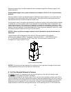
8. Connection of the oil supply and return line piping to the appliance should be made from the
left-hand side of the burner, facing the burner compartment cover.
9. When copper is to be used for fuel oil supply lines, use of continuous runs of heavy wall copper
tubing is recommended. Avoid running tubing against any type of heating unit and across
ceiling or floor joists. If possible, install the tubing under the floor.
10. Where tubing is used for fuel oil supply lines, insure the tubing contains no kinks, sharp bends,
or collapsed regions where the inside cross-sectional area of the tube is greatly reduced. These
will excessively reduce the flow of oil.
11. Flared fittings should be used at all tube joints, when tubing is used for fuel supply lines. Do
not use compression fittings. Avoid the use of tube fittings in inaccessible locations.
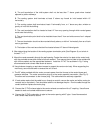
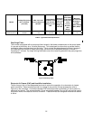
The BF3 burner has been factory set-up for a two pipe system. This means the burner has been
equipped with a by-pass plug. To aid in the installation, twin street-ells have been applied to the burner
oil connections. It is recommended that the installation remain a two-pipe set-up. If there are issues of
difficulties in running a return line to the oil tank it is permissible and recommended to install a de-aerator
such as a Tigerloop Brand for this application. This will ensure there to be no lift issues or problems with
the installation and eliminate the need to run a return pipe back to the tank.
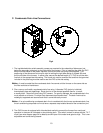
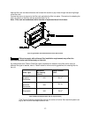
Burners are equipped with a single-stage, fuel pump. This type of fuel pump, when connected with a
supply line only, is satisfactory where the fuel supply is level with, or above the burner thus permitting
gravity flow of oil to the burner. If the tank is above the burner, and gravity oil feed to the burner is
permitted, a single line system may be used. The line should have a gradual slope downward of
approximately 1/2 inch per foot, or more, from the tank to a point directly below where it is connected to