


17
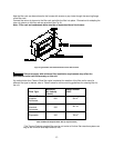
the pump. Pitching the line upward toward the tank will help prevent the formation of air pockets in the
line.
J. ELECTRICAL WIRING:
: This appliance must be grounded in accordance with local codes, or in the absence
of local codes, with the National Electrical Code, ANSI/NFPA 70-1999, or the latest edition.
Electrical Connections
NOTICE: All field wiring must conform to local, state, and national installation codes.
A disconnection switch equipped with overcurrent protection rated at 15 A. (e.g. a time delay-
type fuse or inverse time, circuit breaker) should be installed in the service line for shutting
down and protecting the furnace and electrical system.
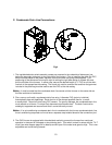
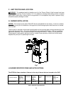
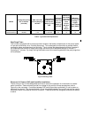
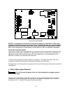
Since the furnace is entirely pre-wired at the factory, it is only necessary to connect the building
electrical service lines to the two (2) pigtail wires extending from the 2x4 junction box. The fan timer
board is mounted inside the furnace blower compartment. The service lines to the furnace should be
no smaller than 14 Ga., insulated copper wire with a temperature rating of 60
0
C, or greater.
Connect an equipment ground wire to the furnace at the 2x4 junction box. If wiring
is run through metal electrical conduit, it may not be necessary to run a separate equipment
ground wire. Consult local codes and authorities for specific minimum requirements.
A two (2) wire connection to the room thermostat from the fan timer board is also
necessary. This is typically a low voltage (24 VAC) circuit. Consult the National Electrical Code,
ANSI/NFPA 70-2002 or latest edition, for guidelines for proper wiring methods and materials for this
circuit.
Refer to the electrical diagrams contained in Appendix B of this manual for an electrical schematic,
a connection diagram, and operating instructions.
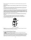
Room Thermostat
A room thermostat is not furnished with this furnace. However, a thermostat is required to properly
operate the furnace control system in a typical residential heating application.
The room thermostat should be located on an interior wall in the natural circulating path of the room
air.
The thermostat should not be installed in a location where it is directly exposed to,
• cold air infiltration, i.e. drafts from outside openings such as windows and doors,
• air currents produced by supply air registers, and
• heat from a nearby source, such as a fireplace, electrical appliances, lamps,
solar radiation, a wall enclosing warm air ducts, a chimney, or a flue gas vent.