


12
blower and blower motor have been selected to work successfully against the following range of duct
system resistance.
Recommended range of duct system resistance for all models: 0.2 to 0.5 in. W. G. external static
pressure.
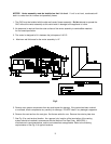
Due to the need to maintain an adequate supply of combustion and ventilation air, the furnace shall not
be installed in small room without return air duct system. A duct the full size of the furnace return aid
opening shall extend to a location outside the furnace room.
If the furnace is used in connection with summer air conditioning (cooling), the furnace should be installed
in parallel with, or on the upstream side of, the evaporator coil to avoid water vapor condensation in the
furnace heat exchanger. If the cooling unit is installed in a parallel flow arrangement, dampers (or other
means used to control airflow) should be provided to prevent chilled air from entering the furnace. If such
damper is manually operated, it must be equipped with a means to prevent operation if either unit, unless
the damper is placed in either the full heat or full cool position.
NOTICE: Return air grilles and supply registers in the air distribution system should never be
obstructed.
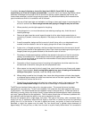
The duct system shall be designed for the maximum CFM requirements of the installation
whether it is for heating of cooling. Two common rules are as follows: 1.) 400 CFM/ton cooling
2.) 14 CFM/1000 BTU’S heating for 55
0
-85
0
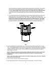
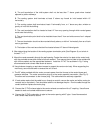
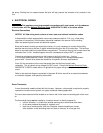
Temp. Rise. The most common location for the
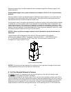
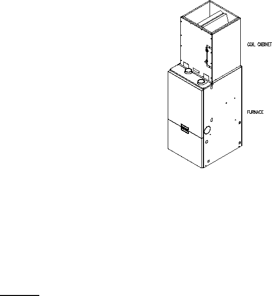
A-shaped coil (A style) is shown in Fig. 5.
Fig-5: Furnace with coil cabinet
NOTICE: The minimum coil pan clearance for a sectional or drum type heat exchanger is three inches
unless specified otherwise by the individual coil manufacturer.
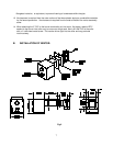
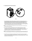
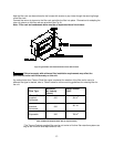
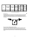
E. Air Filter Mounted External to Furnace:
On highboy furnaces, it is necessary to cut the return air opening in the side, rear casing or base,
depending upon the needs of the specific installation.
The filter rack provided with the furnace, refer to Fig. 6, can serve as a template to scribe a mark for the
return air opening on the casing. Place the filter rack on a side casing approximately one inch up from the
bottom of the furnace and centered from side to side. Place the securing flange against the casing when
locating the return air opening. For your convenience, (3) locator knockouts have been placed at the
proper locations on both the left and right side casings. Cut the opening to the O. D. of the knock-outs.