


8
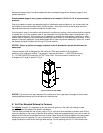
NOTICE: Ventor assembly must be installed so that it is level. If unit is not level, condensate will
leak in to ventor box thru inducer and potentially freeze.
1. The OHC must be installed with the side-wall ventor/ blower assembly. Do Not attempt to operate the
OHC without the ventor assembly as this could result in damage to the appliance or home.
2. No clearance is required from the outer surface of the ventor assembly to combustible materials
for fire hazard prevention.
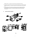
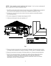
3. The ventor is designed to fit in between the joist space of 16 O.C.
4. Maximum wall thickness for the ventor assembly is 12”.
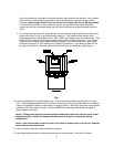
Fig-3
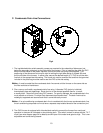
5. Remove vent system components from box and inspect for damage. If the carton has been crushed
or mutilated, check components very carefully for damage. DO NOT install if any damage is apparent.
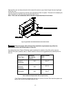
6. Remove the vent tee from the vent pipe. Set the tee aside for now. Remove the exterior plate also.
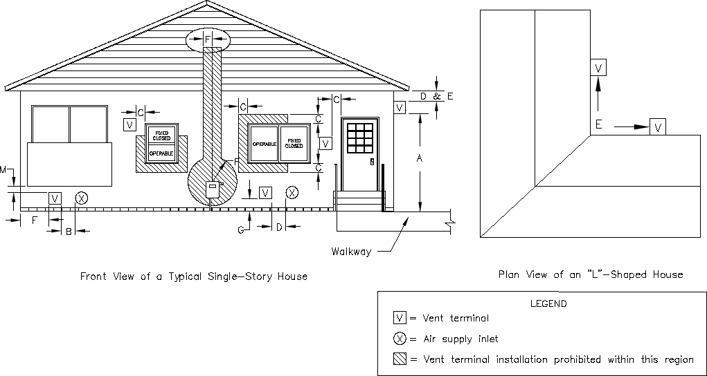
7. See Fig. 3 for vent terminal location. As a general rule, location of the termination of the venting
system should be installed in accordance with the National Fuel Gas Code, ANSI Z223.1,
manufacturer’s recommendations, and/or local codes that are applicable. Refer to the following
requirements or See Fig. 3 for typical locations.