


9
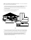
A. The exit termination of the draft system shall not be less than 7’ above grade when located
adjacent to public walkways.
B. The venting system shall terminate at least 3’ above any forced air inlet located within 10’
horizontally.
C. The venting system shall terminate at least 4’ horizontally from, or 1’ above any door, window or
gravity air inlet into the building.
D. The vent termination shall be located at least 12” from any opening through which vented gases
could enter the building.
E. The vent termination point shall not be installed closer than 3’ from an inside corner of an L-shaped
structure.
F. The vent termination should not be mounted directly above, or within 4’ horizontally from an oil tank
vent or gas meter.
G. The bottom of the vent tee outlet shall be located at least 12” above finished grade.
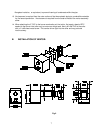
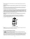
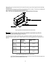
8. After determining the location of the venting system termination point (See Diagram A), cut a hole in
the wall 7” x 7”.
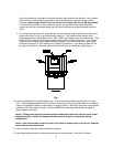
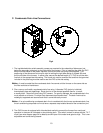
9. Mount the ventor assembly through the wall opening. Fasten the exterior trim plate to the ventor body
with the provided screws and a bead of silicone sealant. Then secure the trim plate to the outside wall
with silicone sealant and the appropriate fasteners. Install the 4” PVC Tee as shown in Fig. 2 using
silicone sealant and a sheet metal screw to secure.
10. Use plumbers strapping or equivalent means to support the ventor main body. When supporting the
main body, care must be taken to ensure the unit is level.
11. The 25” cable provided with the ventor connects power from the furnace to the ventor blower and
pressure switches. The molex connection plugs in to the ventor assembly connection, (See Fig. 2).
The other end is connected to the furnace plug. The cable should be securely supported.
12. If local codes require that the cable be run through a conduit, remove the molex end with a molex pin
removal tool or equivalent. Care should be taken to not damage the pins. Run the cable through the
conduit and then replace the molex plug.
13. Connect the 3” PVC exhaust pipe to the ventor exhaust connection with a 3” coupling. Use silicone
sealant to seal and a sheet metal screw to secure.
14. Connect the 3” PVC combustion air pipe to the ventor opening with 3” pipe. Use silicone sealant
and a sheet metal screw to secure.