


10
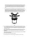
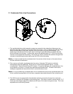
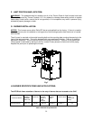
C. Condensate Drain Line Connections:
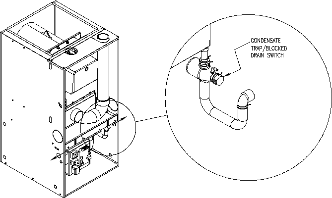
Fig-4
1. The trap/blocked drain switch assembly comes pre-mounted to the underside of blower pan just
below the secondary drain port on the right side of the furnace. Prior to installing the drain, the PVC
elbow must be sealed to the plastic trap with silicone and then the spring clamp applied. This
positioning of the elbow can be turned to right for exiting the right side casing or rotated 180
0
and
exit the left side of the furnace. In either case, secure the desired length of ½” PVC to exit the drain
line hole in the appropriate side casing. The knock-out must be removed first and then the grommet
included in the parts bag must be used to seal the PVC to the side casing.
Notice: It must be noted that the condensate drain line cannot exit the furnace on the same side as
the filter rack due to interference.
2. Plan, source, and install a condensate drain line using ½ diameter PVC (polyvinyl chloride)
thermoplastic pipe and pipefittings. Route the line in the shortest possible manner to reach
a nearby drain. Secure all joints using PVC cement. For gravity drainage, the condensate drain line
must maintain a minimum ¼ inch per foot downward slope toward drain. The drain line must be
watertight, supported and secured such that it cannot be easily moved.
Notice: If an air conditioning condensate drain line is combined with the furnace condensate drain line,
the air conditioning evaporator coil must have a separate trap installed ahead of the connection joint.
3. The OHC furnace is equipped with a blocked drain switch to prevent the furnace from continued
operation in the event of a blocked or slow draining drain. This switch is wired in series with the T & T
circuit (see wire diagram page 54 for details) and will open if the water level gets too high. This is non-
adjustable and cannot be by-passed.