


31
Temco DV1000/1200/1400 Series
76657
Thermo-generator output After the pilot has been lit for approximately three
voltage not within design minutes, and only the thermo-generator wire con-
parameters. nected to the main operator head, measure the
voltage acrossTPTH and TP. This open circuit volt-
age should be between 500mv and 750mv. Tune the
pilot adjustment screw until the mv reding falls with-
in these parameters. (Counterclockwise increases
mv reading, clockwise decreases) If unable to meet
minimum requirements, repalce thermo-generator.
Defective thermostat or (A) With the pilot adjusted properly, ( After the pilot
thermostat wiring has been lit for approximately three minutes, and
only the thermo-generator wire connected to the
main operator head, measure the voltage across
TPTH and TP. This open circuit voltage should be
between 500mv and 750mv. Tune the pilot adjust-
ment screw until the mv reading falls within these
parameters. Counterclockwise increases mv read-
ing, clockwise decreases), place a jumper wire be-
tween TPTH and TH. Take a mv reading across the
TPTH and TP terminals on the valve. This closed
circuit voltage should not fall below 300mv. Record
reading.
(B) Remove jumper wire form the TPTH and TH
connections, and reconnect the thermostat wires to
the same terminals. Take the closed circuit voltage
as described in the previous step. If the mv reading
drops below 150mvm, excessive resistance exists
in the thermostat circuit, and must be isolated and
eliminated.
Thermostat/wall switch Defective wall switch. Repeat the above troubleshooting items covered
will not cycle mian under “Defective thermostat or thermostat wiring”,
burner. except substitute the words “wall switch” where the
word “thermostat” appears in the instructions.
Excessive wire resistance. Make certain that all mv connections are made us-
ing wire of the proper size. (Reference Page 26).
Valve wired wrong. Thermo-generator leads must be connected to the
TPTH and TP connections of the main operator.
Thermostat wires must be connected to the TPTH ,
and TH terminals of the valve.
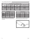
Main burner lights in Main operator coil defective. Verify electrical resistance of main operator coil in
the PILOT position. the following manner.
(A) Remove all wires from operator head.
With an Ohm meter, measure electrical resistance
between TP and TH terminals. If the resistance
does not fall within specification, replace valve.
(See table 1).
Debris on seat of main valve. Replace valve.
Main seat blown out as a Replace valve.
result of exposing LPG gas
valve to unregulated line
pressure in excess of 15 PSI.
Problem Possible Cause Solution
System Checks (continued)