


12
Temco DV1000/1200/1400 Series
76657
T182
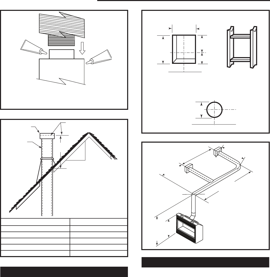
sealant
12/3/03 djt
MILL-PAC
MILL-PAC
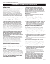
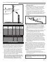
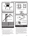
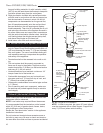
NOTE: Apply sealant “Mill-Pac” to inner pipe and “Mill-Pac” or high
temperature silicone sealant to outer pipe. Sealant should be ap-
plied at every joint in the vent system including at the fireplace and
at the vent terminal.
T182
Fig. 13 Apply sealant at every joint in vent system.
H
12
x
T183
typical straight up
installation
12/3/03 djt
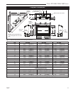
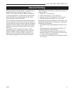
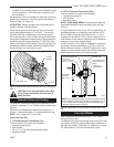
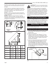
Gas Vent
Vent Cap
Lowest Discharge Opening
Roof Pitch X/12
H (Min.) - Minimum height
from roof to lowest discharge
opening
T183
Roof Pitch H (Min.)
Flat to 6/12 12” (305 mm)
6/12 to 7/12 15” (381 mm)
Over 7/12 to 8/12 18” (457 mm)
Over 8/12 to 16/12 24” (610 mm)
Over 16/12 to 21/12 36” (914 mm)
Fig. 14 Vertical termination location.
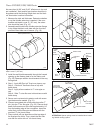
Sidewall (General) Venting Information
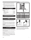
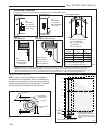
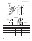
Figures 15 and 16 show examples of horizontal termi-
nation arrangements using two 90° elbows (Rigid Vent).
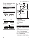
NOTE:
1. A maximum of two 90° elbows are permitted.
2. A minimum of 10’ (3 m) vertical from base of unit is
required if two 90° elbows are used.
3. Minimum distance between elbows is 2’ (610 mm).
4. Determine the permitted range of horizontal ter-
mination arrangement by using chart above and
deducting 3’ (914 mm) from the maximum horizontal
distance for the second 90° elbow.
VO584-100
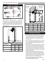
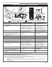
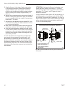
Vent Opening
2/99 djt
Vent Opening for Combustible Wall
9³⁄₄”
(248 mm)
10³⁄₄”
(273 mm)
5⁷⁄₈”
(149 mm)
4⁷⁄₈”
(124 mm)
Fireplace Hearth
Framing Detail
Opening for Noncombustible Wall
Rnd.
8” Dia.
(203 mm)
Min.
Fireplace Hearth
VO584-100
Fig. 15 Locate vent opening on wall.
33"
(838mm)
Minimu
m
53" (1346mm)
Maximum
28' (8.5m)
2' (610mm)
Minimum
B
12" (305mm)
Minimum
A
10' (3m)
Minimum
If length "B" is increased,
length "A" must be decrease
d
by a corresponding amount
T184
sidewall ventin
g
12/3/03 djt
A vent guard should be used
whenever the termination is
lower than the specified mini-
mum or as per local codes.
T184
Fig. 16 Horizontal vent run.
Flex Venting
• Flex vent shall use the spacer springs as included
every foot to ensure proper vent operation.
• The 4” x 7” flex system may be used for all sidewall
applications and vertical venting up to 35’ (10.7 m).
• Flex shall be properly supported so there are no
sags in the system. Supports must be used at least
every 24” (610 mm) on horizontal section and every
36” (914 mm) on vertical. Wire or metal stripping
may be used to support the venting.
• For 4” x 7” flex, the 7” flex has an outside diameter
of 7¹⁄₂” (191 mm) and if installed in a chase the in-
side diameter of the chase should be 9¹⁄₂” (241 mm)
minimum.