


26
Temco DV1000/1200/1400 Series
76657
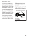
Thermostatic Fan Kit - Optional
(Part # GDVTFK)
For installation of the optional fan, please refer to the
instructions included in the fan kit.
Electrical Services
Optional fan kits are equipped with a 120V, 60Hz
blower, less than 12 amps.
If electrical supply 120V is being roughed in to provide
for future installation of an optional blower kit, an ap-
proved surface mount, steel electrical box, cover and
strain relief bushing must be installed in the fireplace
(supplied by others).
NOTE: All electric connections are to be made in ac-
cordance with CSA Standard C22.1 - Canadian Electri-
cal Code part 1 or with the National Electrical Code,
ANSI/NFPA 70 (latest addition) and/or in accordance
with local codes.
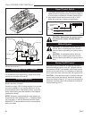
TL121
DV1000/DV1200
final position logs
12/11/03 djt
TL121
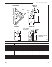
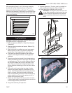
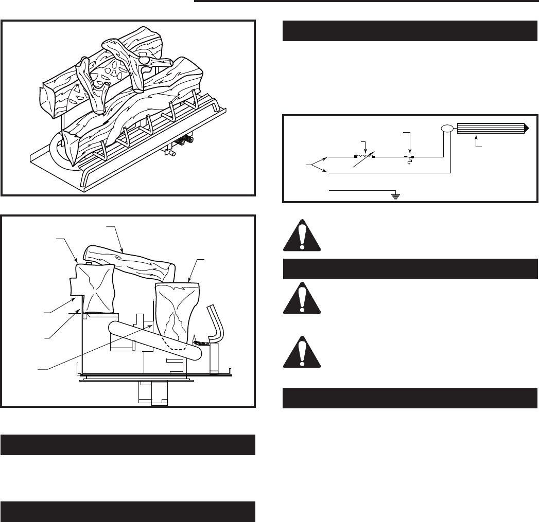
Fig. 34 DV1000 and DV1200 logs in final position.
TL122
Dv logs
side view
12/11/03 djt
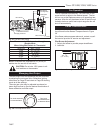
Back Log
Twig
Slot
Bracket
Bracket
Front Log
TL122
Fig. 35 Side view of logset. (NOTE: The side logs for the
DV1400 are not shown.)
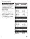
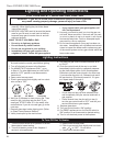
Speed Control Switch
1. The blower combination on/off switch and electronic
speed control is supplied loose to allow mounting in
a conveniently located wall mounted electrical box.
2. Wire speed control into black (hot) side of 120V,
60Hz line as shown in blower wiring diagram.
M
White
Black
T173
blower wiring
11/14/03 djt
G
Green
120
Volt
Speed Control
Switch
Temperature
Sensor
Fan
T173
Fig. 36 Fan wiring diagram.
CAUTION: Should this fan require servic-
ing, the power supply must be discon-
nected.
Millivolt System
CAUTION: At installation and/or after any
service work or repairs glass door must be
removed before proceeding to lighting instruc-
tions.
CAUTION: At installation and/or after any
service work or repairs glass door must be
removed before proceeding to lighting instruc-
tions.
Burner On/Off Control
All models may be used with an optional wall switch
that turns the main burner on or off. Optional millivolt
thermostats (GFPMT) and remote control may be sub-
stituted for the wall switch (For installation of these op-
tions, detail instructions are provided with optional kits).
CAUTION: If the remote receiver is located in the gas
control area (under the firebox), clearance should be
below the firebox at least 2” (51 mm) to avoid high tem-
peratures (receiver should not be exposed to tempera-
tures exceeding 130°F).