


Performance Tests
TDS 520A, 524A, 540A, & 544A Performance Verification
b.
Check against limits:
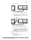
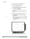
CHECK that the readout Ch2 Pk-Pk is between 90 mV and
110 mV, inclusive.
Press VERTICAL MENU; then press the side-menu button to
toggle to the 50 setting.
Set vertical SCALE to 10 mV; then press CLEAR MENU.
CHECK that the readout Ch2 Pk-Pk is between 45 mV and
55 mV, inclusive.
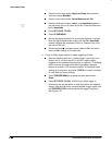
4.
Disconnect the hookup:
Disconnect the cable from the generator output
at the input connector of the channel last tested.
Check Probe Compensator Outputs
One female BNC to clip adapter (Item 15), two dual-banana connectors (Item
5), one BNC T connector (Item 6), two 50 precision cables (Item 4), and
one DC calibration generator (Item 8).
Prerequisites:
See page 1-15. Also, this Digitizing Oscilloscope must have
passed
Check Accuracy — Long-Term Sample Rate, Delay time, Time Mea-
surement
on page 1-39 and
Check Accuracy for DC Gain and Voltage Mea-
surements
on page 1-25.
Procedure:
1.
Install the test hookup and preset the instrument controls:
a.
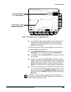
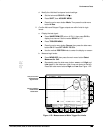
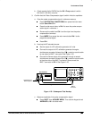
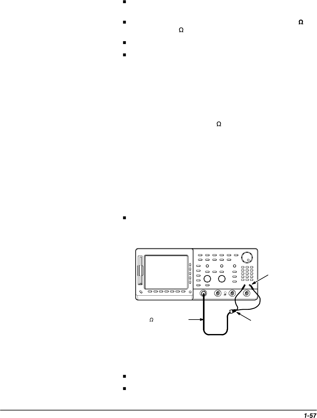
Hook up test-signal:
Connect CH 1 to PROBE COMPENSATION SIGNAL and to
PROBE COMPENSATION GND through a precision coaxial
cable and a BNC to clip adapter. See Figure 1-23.
50 Coaxial Cable
Female BNC to
Clip Adapter
Black Lead
to GND
Figure 1-23: Initial Test Hookup
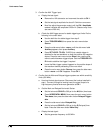
b.
Initialize the oscilloscope:
Press save/recall SETUP.
Press the main-menu button Recall Factory Setup.