


Performance Tests
Performance Verification Procedures
Follow these rules to match this procedure to the model of the oscillo-
scope under test:
Models TDS 540A, 544A Only—When using Table 1-2 to test
CH 1—CH 4; ignore the columns for AUX 1 & AUX 2 settings and
limits.
Model TDS 520A, 524A Only—Use Table 1-2 to test input channels;
use the columns for CH 1—CH 4 when testing CH 1 and CH 2; use
the columns for AUX 1 and AUX 2 when testing those channels.
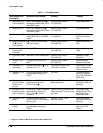
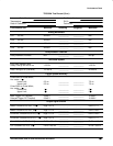
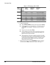
Table 1-2: DC Offset Accuracy (Zero Setting)
Vertical Scale
Setting
Vertical
Position
Offset Accuracy Limits
CH 1 –
CH 4
AUX 1 &
AUX 2
and Offset
Setting
1
CH 1 – CH 4 AUX 1 & AUX 2
1mV
100 mV 0 mV mV
100 mV 1 V 0 mV mV
1V 10 V 0 mV V
1
Vertical position is set to 0 divisions and vertical offset to 0 V when the oscilloscope is
initialized in step 1.
b.
Set the vertical scale:
Set the vertical SCALE to one of the settings
listed in Table 1-2 that is not yet checked. (Start with the first setting
listed.)
c.
Display the test signal:
The baseline DC test level was initialized for
all channels in step 1 and is displayed as you select each channel
and its vertical scale. Be sure
not
to use the vertical POSITION knob
while checking any channel for accuracy of offset, since varying the
position invalidates the check.
d.
Measure the test signal:
Rotate the general purpose knob to superim-
pose the active cursor over the baseline DC test level. (Ignore the
other cursor.)
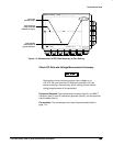
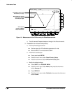
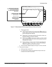
e. Read the measurement results at the absolute (@:) cursor readout,
not the delta ( :) readout on screen (see Figure 1-4).
f.
Check against limits:
Do the following subparts in the order listed.
CHECK that the measurement results are within the limits listed
for the current vertical scale setting.
Repeat substeps b through f until all vertical scale settings set-
tings listed in Table 1-2 are checked for the channel under test.
g.
Test all channels:
Repeat substeps a through f for all input channels.
3.
Disconnect the hookup:
No hookup was required.