


Brief Procedures
TDS 520A, 524A, 540A, & 544A Performance Verification
e.
Test all channels:
Repeat substeps a through d to verify AUX 2.
4.
Remove the test hookup:
Disconnect the probe from the channel input
and the probe-compensation terminals.
Verify the Time Base
Equipment Required:
One P6139A probe.
Prerequisites:
None.
Procedure:
1.
Install the test hookup and preset the oscilloscope controls:
a.
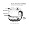
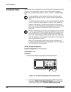
Hook up the signal source:
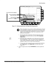
Install the probe on CH 1. Connect the
probe tip to PROBE COMPENSATION SIGNAL on the front panel;
connect the probe ground to PROBE COMPENSATION GND. (See
Figure 1-3 on page 1-6.)
b.
Initialize the oscilloscope:
Press save/recall SETUP.
Press the main-menu button Recall Factory Setup; then press
the side-menu button OK Confirm Factory Init.
c.
Modify default settings:
Press AUTOSET
to obtain a viewable, triggered display.
Set the horizontal SCALE to 200 s.
Press CLEAR MENU to remove the menus from the screen.
2.
Verify that the time base operates:
Confirm the following statements.
a. One period of the square-wave probe-compensation signal is about
five horizontal divisions on-screen for the 200 s horizontal scale
setting (set in step 1c).
b. Rotating the horizontal SCALE knob clockwise expands the wave-
form on-screen (more horizontal divisions per waveform period), and
that counterclockwise rotation contracts it, and that returning the
horizontal scale to 200 s returns the period to about five divisions.
c. The horizontal POSITION knob positions the signal left and right
on-screen when rotated.
3.
Remove the test hookup:
Disconnect the probe from the channel input
and the probe-compensation terminals.