


Performance Tests
Performance Verification Procedures
The procedure that follows checks those characteristics of the output signals
that are listed as checked under
Warranted Characteristics
in Section 2,
Specifications.
The oscilloscope outputs these signals at its front and rear
panels.
Check Outputs — CH 3 and Main and Delayed Trigger
(TDS
540A and 544A only)
Equipment Required:
Two 50 precision cables (Item 4), and one calibra-
tion generator (Item 9).
Prerequisites:
See page 1-15. Also, this Digitizing Oscilloscope must have
passed
Check Accuracy — Long-Term Sample Rate, Delay time, Time Mea-
surement
on page 1-39 and
Check Accuracy for DC Gain and Voltage Mea-
surements
on page 1-25.
Procedure:
1.
Install the test hookup and preset the instrument controls:
a.
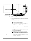
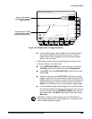
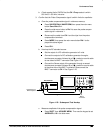
Hook up test-signal source 1:
Connect the standard amplitude output of a calibration generator
through a 50 precision coaxial cable to CH 3. See Figure 1-21.
Set the output of the calibration generator to 0.500 V.
b.
Hook up test-signal source 2:
Connect the Main Trigger Out at the
rear panel to CH 2 through a 50 precision cable. See Figure 1-21.
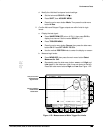
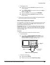
50 Coaxial Cables
To Main
Trigger Out
Calibration
Generator
Output
Figure 1-21: Initial Test Hookup
c.
Initialize the oscilloscope:
Press save/recall SETUP.
Press the main-menu button Recall Factory Setup.
Press the side-menu button OK Confirm Factory Init.
Output Signal Checks