


Typical Characteristics
TDS 520A, 524A, 540A, & 544A Performance Verification
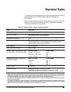
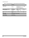
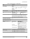
Table 2-15: Typical Characteristics — Triggering System
Name
Description
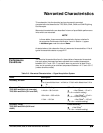
Accuracy, Trigger Level or Thresh-
old, DC Coupled
Trigger
Source
Any Channel
Auxiliary
(TDS 540A &
544A only)
Accuracy
2
Offset) + 0.3 div volts/div
setting + Offset Accuracy)
mV)
Input, Auxiliary Trigger
The input resistance is 1.5 k ; the maximum safe input voltage is
AC).
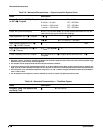
Trigger Marker Position, Edge Trigger-
ing
Acquire Mode
Sample, Hi-Res, Average
Peak Detect, Envelope
Trigger-Position Marker
1,2
WI + 1 ns)
ns)
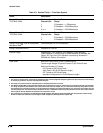
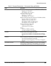
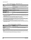
Holdoff, Variable, Main Trigger Minimum: For any horizontal scale setting, the
minimum
holdoff is
10 times that setting, but is never less than 1 s or longer than 5 s.
Maximum: For any horizontal scale setting, the
maximum
holdoff is at
least 2 times the minimum holdoff for that setting, but is never more
than 10 times the minimum holdoff for that setting.
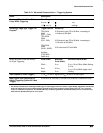
Width, Minimum Pulse and Rearm, for
Logic Triggering or Events Delay
3
5 ns
Lowest Frequency for Successful Op-
eration of “Set Level to 50%” Function
30 Hz
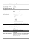
Sensitivity, Edge Trigger, Not DC
Coupled
4
Trigger Coupling
AC
Noise Reject
High Frequency Reject
Low Frequency Reject
Typical Signal Level for
Stable Triggering
Same as DC-coupled limits
5
for frequen-
cies above 60 Hz. Attenuates signals be-
low 60 Hz.
Three and one half times the DC-coupled
limits.
5
One and one half times the DC-coupled
limits
5
from DC to 30 kHz. Attenuates sig-
nals above 30 kHz.
One and one half times the DC-coupled
limits
5
for frequencies above 80 kHz. At-
tenuates signals below 80 kHz.
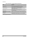
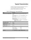
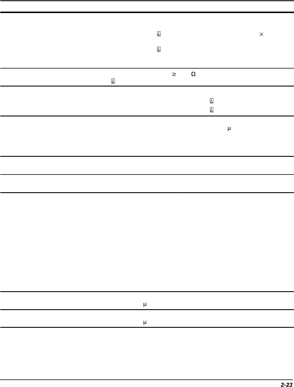
Sensitivities, Logic-Type Trigger/Events
Delay, DC Coupled
6
1.0 division, from DC to 100 MHz with a minimum slew rate of
25 divisions/ s at the trigger level or the threshold crossing.
Sensitivities, Pulse-Type Runt Trigger
6
1.0 division, from DC to 200 MHz with a minimum slew rate of
25 divisions/ s at the trigger level or the threshold crossing.