


Performance Tests
Performance Verification Procedures
c.
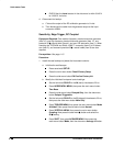
Check Main Trigger output against limits:
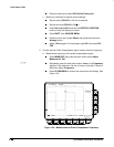
CHECK that the Ch2 High readout is 2.5 volts and that the
Ch2 Low readout is 700 mV.
Press VERTICAL MENU; then press the main-menu button
Coupling. Now press the side-menu button to toggle it to the
50 setting.
CHECK that the Ch2 High readout is 1.0 volt and that the Ch2
Low readout 250 mV.
d.
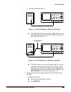
Check Delayed Trigger output against limits:
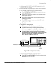
Move the precision 50 cable from the Main Trigger Output
BNC to the Delayed Trigger Output BNC.
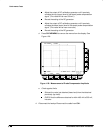
CHECK that the Ch2 High readout is 1.0 volt and that the Ch2
Low readout 250 mV.
Press the side-menu button select the 1 M setting.
Press CLEAR MENU.
CHECK that the Ch2 High readout is 2.5 volts and that the
Ch2 Low readout is 700 mV.
3.
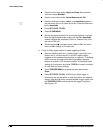
Confirm CH 3 output is within limits for gain:
a.
Measure gain:
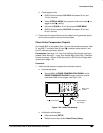
Move the precision 50 cable from the rear-panel DELAYED
TRIGGER OUTPUT BNC to the rear-panel SIGNAL OUTPUT
BNC.
Push SHIFT. Then push DELAYED TRIG.
Press the main-menu button Source. Then press the side-menu
button Ch3.
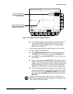
Push HORIZONTAL MENU.
Push the main-menu button Time Base. Then press the side-me-
nu button Delayed Triggerable.
Set vertical SCALE to 100 mV.
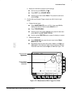
Press MEASURE; then press the main-menu button Select
Measrmnt for
Ch2
.
Repeatedly press the side-menu button –more– until Pk-Pk
appears in the side menu (its icon is shown at the left). Press the
side-menu button Pk-Pk.
Press CLEAR MENU.