


Performance Tests
TDS 520A, 524A, 540A, & 544A Performance Verification
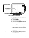
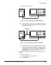
Set the test signal amplitude for about five divisions on screen.
Now fine adjust the generator output until the CH 1 Amplitude
readout indicates the amplitude is 500 mV. (Readout may fluctu-
ate around 500 mV.)
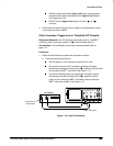
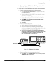
Disconnect the leveling head at CH 1 and reconnect it to CH 1
through a 5X attenuator.
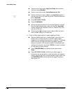
d. Repeat step 2, substeps b and c only, since only the 500 MHz fre-
quency is to be checked here.
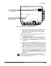
5.
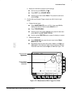
Confirm that the Main and Delayed trigger systems couple trigger signals
from all channels:
Doing the procedure
Check Analog Bandwidth,
which
begins on page 1-32, checks coupling. If you have not done that proce-
dure, do so after finishing this procedure. See the following note
.
NOTE
Steps 1 through 4 confirmed trigger sensitivity for the Main and
Delayed triggering systems using the CH 1 input. Doing the proce-
dure
Check Analog Bandwidth
ensures that trigger signals are
coupled from all four channels.
When checking delayed triggering sensitivity at 500 MHz, the
waveform record may have some missing interpolated record
points. The waveform is still stably triggered. (See definition of a
stable trigger earlier in this procedure.)
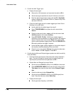
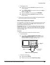
6.
Disconnect the hookup:
Disconnect the cable from the generator output
at the input connector of the channel last tested.