


NOTE: DIAGRAMS & ILLUSTRATIONS ARE NOT TO SCALE.
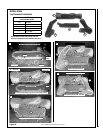
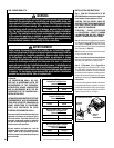
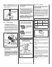
Step 6. See Figure 60 and remove the pilot
hood assembly to access the hexed pilot orifice.
Remove and replace the orifice with the one
provided with the kit.
37
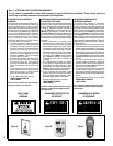
Use a 7/16" open end wrench and turn the
pilot hex fitting counter-clockwise 1/4 turn.
(See Figure 63).
Note - The orifice strip tab may be randomly
located on any side of the hex fitting.
c. Push the orifice strip tab all the way
against the hex fitting to align the appropri-
ate gas type orifice (see Figures 62 and 63).
The type of gas for which the pilot is set,
is, the gas type shown on the tab.
d. Retighten, clockwise, the pilot hex
fitting until the pilot hood aligns with the
thermocouple and thermopile as indicated
by the arrows shown in Figure 63.
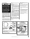
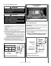
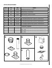
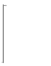
Adjusting Knob
Conversion screw
(blue natural gas;
red LP/propane gas)
Regulator Cap
Honeywell Millivolt Gas Valve
Figure 61
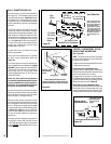
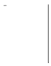
Pilot for Honeywell Millivolt Gas Valve
Figure 62
b. Convert the pilot orifice as follows (see
Figures 62 and 63):
Note - Use extra care not to engage the
orice strip with the 7/16" open end wrench
(contacting the orifice strip could cause strip
distortion rendering the pilot inoperative).
Also avoid wrench contact to any of the
other pilot parts.
Millivolt Appliances
Step 7 - Honeywell Systems
a. Convert the gas valve as follows
(see Figure 61): Remove the plastic protect-
ing cap. Remove the gas type setting screw
by turning it counterclockwise. Obtain the
replacement gas type setting screw from the
kit and screw it into place (red for propane
and blue for natural gas). Tighten the gas type
setting screw by turning it clockwise. Replace
the plastic protecting cap.
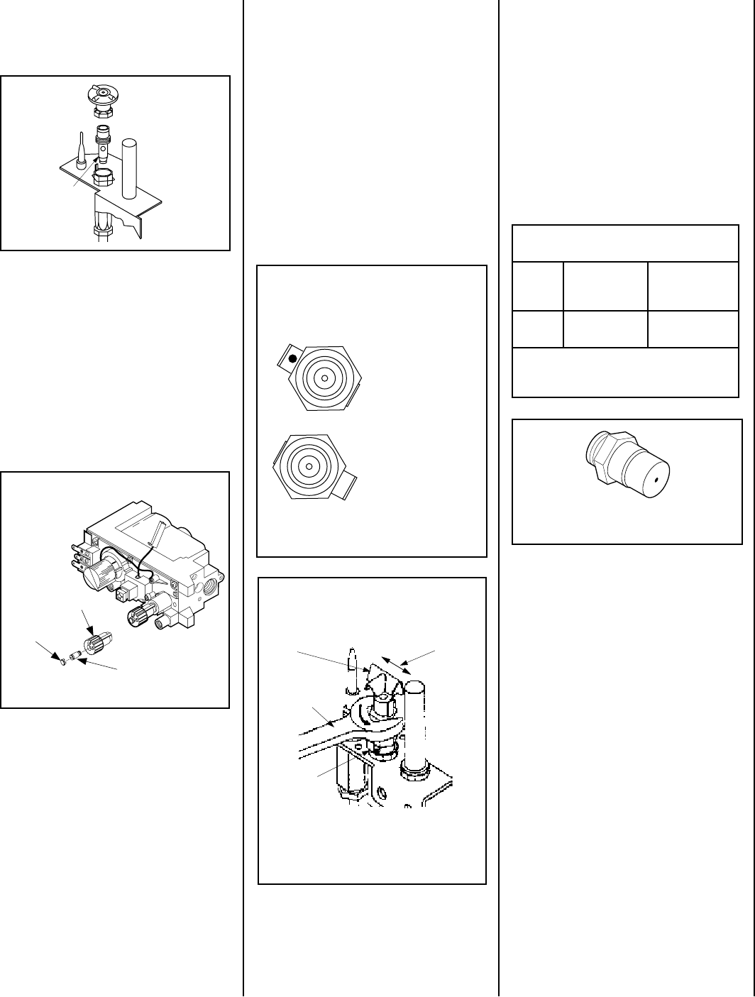
Pilot for Honeywell Millivolt Gas Valve
(Loosening of Hex Fitting For
Orifice Strip Tab Positioning)
Figure 63
7/16 in. Open
End Wrench
Hood
Hood
Alignment
Orifice
Strip Tab
Take care not to contact the orifice strip tab
with the hex fitting wrench - distortion of the
tab may render the pilot inoperative.
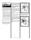
LP (propane) Gas Posi-
tion - 1/16 inch hole,
LP and red color shown
on tab.
Natural Gas Position
- NAT shown on tab.
Top View of Hex Fitting and Orifice Strip Tab
Orifice Strip Tab Position Identification
For LP (propane gas) and Natural Gas
P
L
NAT
Pilot for SIT Millivolt
Gas Valve
Figure 60
Pilot
Orifice
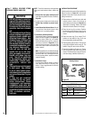
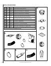
Figure 64 - Burner Orifice
Step 9. Reassemble the remaining components
by reversing the procedures outlined in the
preceding steps.
Step 10. Attach the conversion label provided
in the conversion kit to the rating plate on the
appliance.
Step 11.Turn on gas supply and test for gas
leaks. See Test All Connections For Gas Leaks
on Page 27.
Step 12. Attach manometer to the manifold side
pressure test fitting and verify manifold pres-
sure reads 3.5 inches water column (0.87 kPa)
for natural gas, and 10.0 inches water column
(2.49 kPa) for propane gas.
ALWAYS TEST PRESSURES WITH THE VALVE
REGULATOR CONTROL AT THE HIGHEST
SETTING.
Step 8. (Refer to Figure 64)
VERIFY THE PROPER ORIFICE SIZE BE-
FORE INSTALLING IT.
Remove the burner orifice from the manifold
and replace it with the one provided with the
kit. See Table 10 for orifice sizes required for
use with natural gas or propane gas. Figure 64
illustrated the orifice. Use pipe joint compound
or Teflon tape on all pipe fittings before install-
ing (ensure propane resistant compounds are
used in propane applications, do not use pipe
joint compounds on flare fittings).
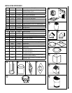
Burner Orifice Sizes
Elevation 0-4500 feet ( 0-1372 meters)
Model
Natural
Gas
drill size (inches)
Propane
Gas
drill size (inches)
SDV35
2.3 mm (.090")
*
37L70 •
#54 (.055")
*
99K79 •
* Standard size installed at factory
• Part /Cat. Number
Table 10