


NOTE: DIAGRAMS & ILLUSTRATIONS ARE NOT TO SCALE.
21
H
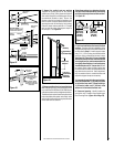
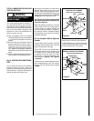
H = 28 in. (711 mm) Maximum.
7 in. (178 mm)
�
When using Secure Flex,
use Firestop/Spacer
SF4.5HF
�
Wall Firestop/Spacer
(SV4.5HF)
H
V
Wall Firestop/Spacer
(SV4.5HF)
When using Secure Flex,
use Firestop/Spacer
SF4.5VF.
Ceiling
Firestop/Spacer
(SV4.5VF)
When using Secure Flex,
use Firestop/Spacer
SF4.5HF.
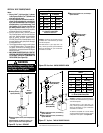
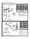
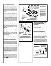
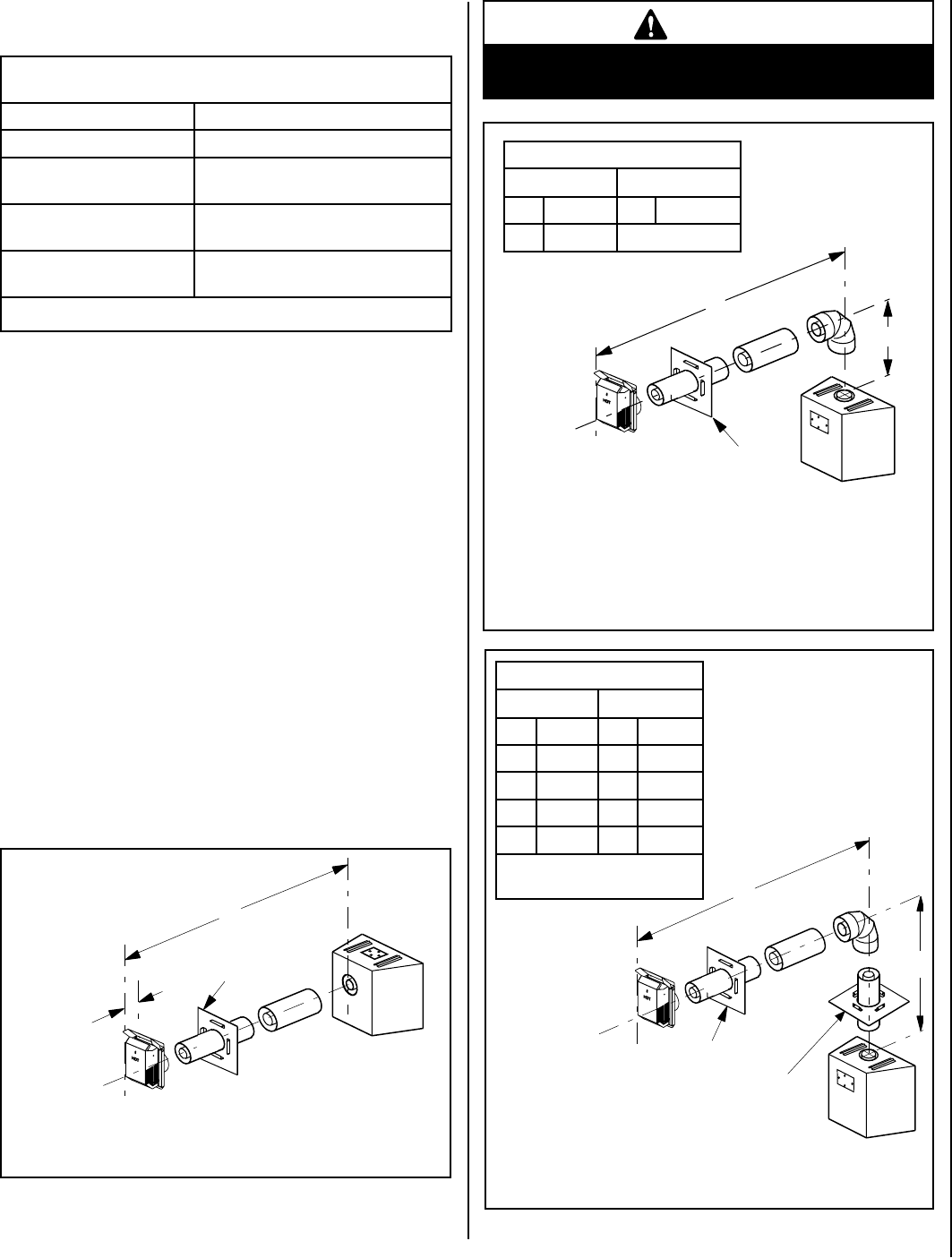
Figure 38 - Top Vent -
ONE 90 DEGREE ELBOW - ELBOW CONNECTION AT APPLIANCE
Figure 39 - Top Vent - ONE 90 DEGREE ELBOW -
ELBOW CONNECTION NOT DIRECTLY AT APPLIANCE
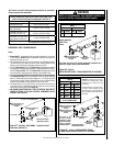
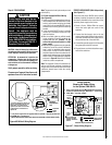
Figure 37 - Rear Vent - NO ELBOWS - Square Horizontal
Termination (SV4.5HT-2)
See Table 8 as an aid in venting component selection for a
particular range of exterior wall thicknesses.
See Table 8 as
an aid in venting
component selec-
tion for a particular
range of exterior
wall thicknesses.
H
�
Wall
Firestop/Spacer
(SV4.5HF)
V
�
When using Secure Flex,
use Firestop/Spacer
SF4.5HF
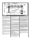
HORIZONTAL VENT FIGURES/TABLES
Notes:
• Secure Vent™ components (rigid vent pipe and terminal) are shown
in the Figures; Secure Flex™ components (flexible vent pipe and
terminal) may also be used.
• Two 45 degree elbows may be used in place of one 90 degree elbow.
The same rise to run ratios, as shown in the venting Figures for 90
elbows, must be followed if 45 degree elbows are used.
• SV4.5VF (Secure Vent), SF4.5VF (Secure Flex) firestop/spacer must be
used anytime vent pipe passes through a combustible floor or ceiling.
SV4.5HF (Secure Vent), SF4.5HF (Secure Flex) firestop/spacer must
be used anytime vent pipe passes through a combustible wall.
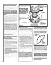
• It is very important that the horizontal/inclined run be maintained
in a straight (no dips) and recommended to be in a slightly elevated
plane, in a direction away from the fireplace of 1/4" rise per foot (20
mm per meter) which is ideal, though rise per foot run ratios that are
smaller are acceptable all the way down to at or near level.
• The tables show a 1(V) to 5(H) ratio up to a maximum horizontal run
of 20 feet except for installations where an elbow is the only vertical
vent section in the system (see Figure 38).
• AN ELBOW IS ACCEPTABLE AS 1 FOOT OF VERTICAL RISE EXCEPT
WHERE AN ELBOW IS THE ONLY VERTICAL COMPONENT IN THE
SYSTEM. See Figure 38.
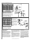
Square termination
(SV4.5HT-2)
shown
See Table 8 as an aid in venting component selection for a particular
range of exterior wall thicknesses.
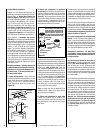
WARNING
Under no circumstances, may separate sections of
concentric flexible vent pipe be joined together.
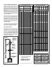
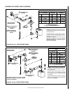
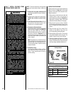
Table G
H Maximum
V Minimum
feet (meter) feet (meter)
5 (1.524) 1 (0.305)
10 (3.048) 2 (0.610)
15 (4.572) 3 (0.914)
20 (6.096) 4 (1.219)
V + H = 40 feet (12.2 m) Max.
H = 20 ft. (6.096 m) Max.
Square termination
(SV4.5HT-2) shown.
Square termination
(SV4.5HT-2) shown.
Table F
H Maximum V Minimum
feet (meter) feet (meter)
3 (0.914) Elbow Only
Example: If 20 feet of (H) horizon-
tal vent run is needed, then 4 feet
minimum of (V) vertical vent will
be required.
This table shows a 1(V) to 5(H) ratio.
For every 1 foot of vertical, you are
allowed 5 feet of (H) horizontal run
up to a maximum (H) horizontal run
of 20 feet.
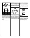
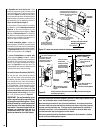
Venting Components Required for Various Exterior Wall Thick-
nesses, when using Square Termination Kit (SV4.5HT-2)
Vent Components Required Exterior Wall Thickness - inches (mm)
Termination Kit Only 6 to 9-1/4 (152 to 235)
Termination Kit and 6 In. Vent
Section (SV4.5L6)
10-3/4 to 14 (273 to 356)
Termination Kit and 12 in.
Vent Section (SV4.5L12)
16-3/4 to 20 (426 to 508)
Termination Kit and Tele-
scopic Section (SV4.5L12)
11-3/4 to 20 (299 to 508)
Table 8
Note: See Figure 36 showing wall thickness range
when using SV4.5HT-2 termination kit only.