


15
NOTE: DIAGRAMS & ILLUSTRATIONS ARE NOT TO SCALE.
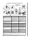
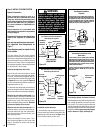
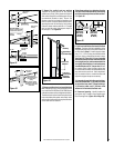
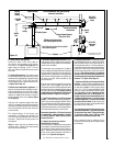
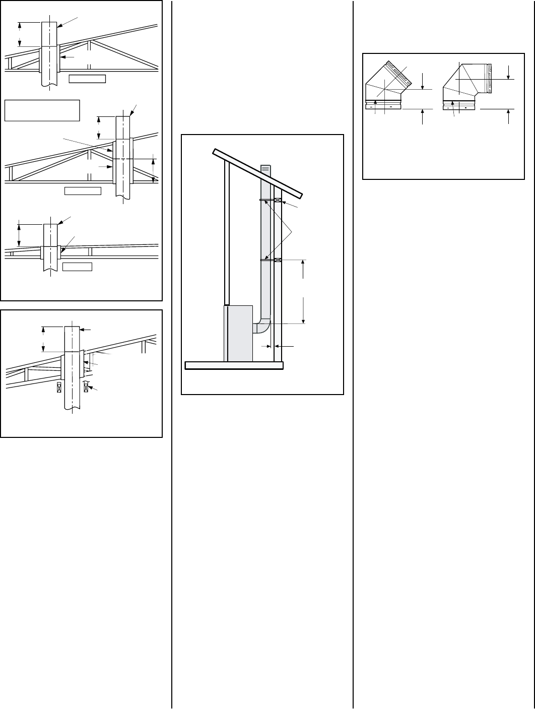
Note: Trim Thimble/
Extension To Desired Length
And Pitch At The Roof Line
14" Min.
Pitched Roof
Pitched Roof
Bow Roof
14" Min.
Outer Pipe Of
Chimney
Outer Pipe Of
Chimney
Outer Pipe Of
Chimney
14" Min.
Firestop
Thimble
Extension
13"
Firestop
Thimble
Firestop
Thimble
Thimble
SV-FSTFE
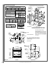
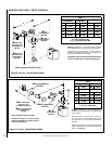
G. Continue installation of horizontal/inclined
sections - Continue with the installation of the
straight vent sections in horizontal/inclined run
as described in Step C. Install support straps
every 5 ft. (1.52 m) along horizontal/inclined
vent runs using conventional plumber’s tape.
See Page 19, Figure 34. It is very important
that the horizontal/inclined run be maintained
in a straight (no dips) and recommended to be
in a slightly elevated plane, in a direction away
from the fireplace of 1/4 " rise per foot (20 mm
per meter) which is ideal, though rise per foot
run ratios that are smaller are acceptable all the
way down to at or near level. Use a carpenter’s
level to measure from a constant surface and
adjust the support straps as necessary.
It is important to maintain the required clear-
ances to combustibles: 1" (25 mm) at all sides
for all vertical runs; and 3" (76 mm) at the top,
1" (25 mm) at sides, and 1" (25 mm) at the
bottom for all horizontal/inclined runs.
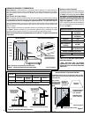
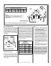
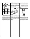
H. Frame roof opening - Identify location for
vent at the roof. Cut and/or frame opening per
Roof Framing Chart (Figure 26 on Page 16).
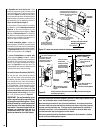
Twist elbow sections in a clockwise direction
only so as to avoid the possibility of unlocking
any of the previously connected vent sections.
See Figure 25.
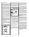
Figure 25
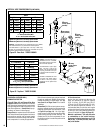
7-5/8”
(194 mm)
4-13/16
(122 mm)
Swivel Joint
(360° swivel)
SV4.5E45
45° Elbow)
Swivel Joint
(360° swivel)
SV4.5E90
90° Elbow)
(206 mm)
8-1/8"
F. Change vent direction to horizontal/inclined
run - At transition from or to a horizontal/inclined
run, install the SV4.5E45 and SV4.5E90 elbows
in the same manner as the straight vent sections.
The elbows feature a twist section to allow them
to be routed about the center axis of their initial
collar section to align with the required direction
of the next vent run element.
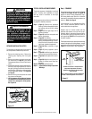
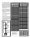
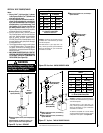
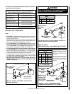
Blocking
Support Straps
(Plumber's tape)
8 feet (2.4 m)
Maximum
1 inch (25.4
mm) minimum
clearance to
combustibles
Figure 24
Figure 22
14" Min.
Outer Pipe Of
Chimney
Use correct firestop
thimble depending on the
pitch of the interior
ceiling.
Note: Regular Thimble
(SV-FSTFE) Can Be Used
If A Header Is Constructed
At This Point
Figure 23
E. Support the vertical vent run sections
-Support the vertical portion of the venting
system every 8 feet (2.4m) above the fireplace
vent outlet using field provided support straps
(conventional plumber's tape). Secure the
plumber's tape to the framing members with
nails or screws. Loop the tape around the vent,
securing the ends of the tape to the framing.
If desired, sheet metal screws #6 x 1/2" length
may be used to secure the support straps to
the vent pipe. See Figure 24.