18
NOTE: DIAGRAMS & ILLUSTRATIONS ARE NOT TO SCALE.
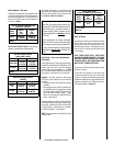
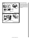
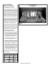
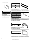
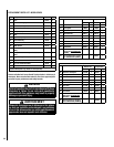
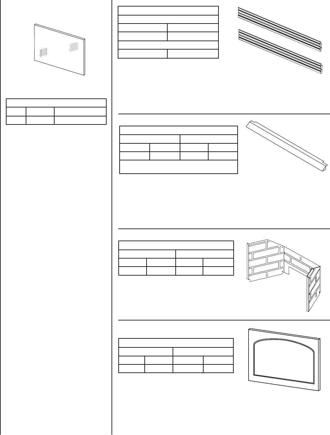
Polished Brass & Brushed Stainless Hood Kits
Attractive hoods are available in two styles. These hoods are designed to be fitted to the glass viewing sides
of the appliance. In addition to providing an aesthetically pleasing appearance to your appliance installation,
the hood reduces heat effects to decorative mantles and finish materials located above the fireplace opening.
The hood kit replaces the standard hood that comes with these appliances and snaps into place. These kits
can be retrofitted to previously installed appliances.
(ref. Form #504,142M)
Eyebrow Hood Kits
Polished Brass Brushed Stainless
Cat. # Model Cat. # Model
96K67 EB35PB 88L49 EB35BS
* These hood kits replace the standard hood that comes with
these fireplaces.
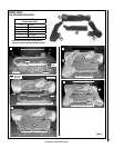
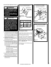
Interior Brick Liner Kits
The brickade liner kits include tan stamped sheetmetal panels for the rear and
side walls of the firebox. The panels have brick-like features in relief. These kits
can be retrofitted into previously installed appliances.
Interior Brick Liner Kits
Rear Vent Top Vent
Cat. # Model Cat. # Model
80L03 BLK-5R 80L01 BLK-5T
(ref. Form #750,023M)
Arch Door Kits
The arch door kits are easy to install and do not require hardware to attach them to the standard door frame.
The decorative arch kits can not be used in conjunction with the screen panel kit.
(ref. Form # 750,021M)
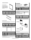
Arch Door Kit
Polished Brass Brushed Stainless
Cat. # Model Cat. # Model
26M43 ADK35CMPB 26M44 ADK35CMBS
* Assembled 8-Piece Louver Kits
Polished Brass
Cat. # Model
H1524 LK-500B
Brushed Stainless
H1525 LK-500BS
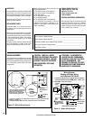
Polished Brass & Brushed Stainless Louvers Kits
These kits include a top 4-louver assembly and a bottom 4-louver assembly. They provide a touch of elegance.
These kits can be retrofitted to previously installed appliances.
(ref. Form # 750,166M)
* Superior Nameplate Logo, 56L93, is not included.
ACCESSORY COMPONENTS
(ref. Form # 750,101M)
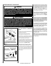
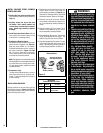
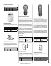
Barrier Screen Panel Kit
Cat. No. Model Description
26M48 HG35M Barrier Screen Panel Kit
Barrier Screen Panel Kit
This easy to install optional screen panel installs over
the standard glass enclosure panel and provides a bar-
rier to prevent direct contact with the hot glass surface.
These screen panels cannot be used in conjunction
with the arch door kits or door frame kits.