


10
NOTE: DIAGRAMS & ILLUSTRATIONS ARE NOT TO SCALE.
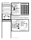
FIREPLACE SPECIFICATIONS
Vent Size
Co-axial DV Vent Size
4-1/2" Inner
7 1/2" Outer
Notes
* The Steady State Efficiency numbers based on
maximum vent configuration.
Diagrams, illustrations and photographs are not to
scale – consult installation instructions. Product
designs, materials, dimensions, specifications,
colors and prices are subject to change or
discontinuance without notice.
Efficiencies
Natural Gas Propane
Model EnerGuide Steady
State
AFUE EnerGuide Steady
State
AFUE
SDV35 55 67 63 60 68 64
Input (BTU/HR)
Natural (NG) &
Propane (LP) Gas
Model Fuel Input Rate (BTU / HR)
SDV35
NG
High 23,000
Low 17,500
LP
High 23,000
Low 17,500
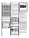
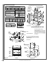
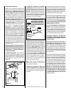
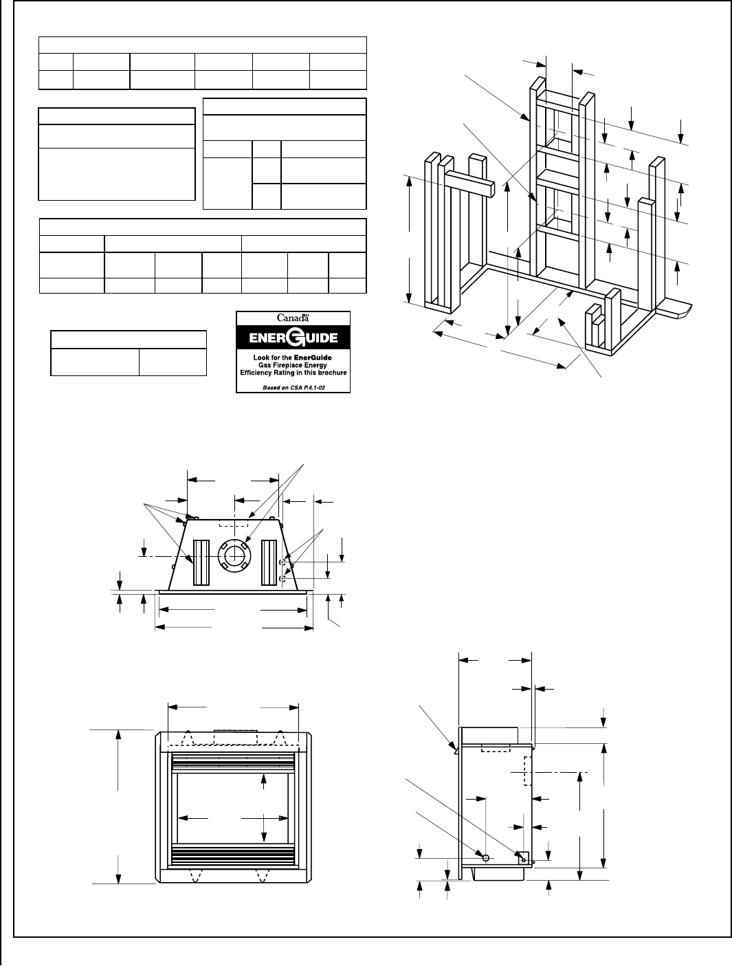
Framing Dimensions - Inches (millimeters)
Model A B C D E
SDV35 42-1/4 (1073) 37-1/2 (953) 23-3/4 (603) 42-1/4 (1073) 16" (406)
Figure 12
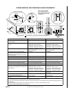
** Framing with Square Horizontal Terminaion SV4.5HT-2
9
(229)
24-7/8
(632)
40 (1016)
32-1/8
(816)
24-7/32
(615)
16
(406)
(13)
1-5/8
(42)
9
(229)
5-9/16
3/16
(141)
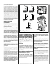
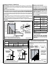
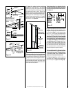
Top View
NOTE -
Hood shown as positioned
in louvered front model.
CO
N
C
ENTRI
C
FLUE
FLUE - 4 -1/2 (114)
COMBUSTION AIR - 7-1/2 (190)
FRAMING
SPACERS
(Top and Sides
and Rear)
GAS INLET
(Either Side
and bottom)
Front View
2-1/2 (63)
(Louvered Front Model Shown)
ELECTRICAL
INLET
2-3/4 x 2 (70 x 51)
Ri
g
ht Side View
(14)
43 (1092)
12-7/16
9/16
(316)
Inches (Millimeters)
(5)
29-1/2
(749)
19
(406)
35-1/8 (892)
37-5/32
(944)
Overall
unit
height
Note - J-box can be relocated in either the right front
or left front corners of the appliance by relocating the
moveable J-box plate.
5-3/8 (137)
Bottom Gas Inlets
8 -1/2
(216)
6
-3/4
1/2
(171)
3-3/8
(86)
A
B
D
7
(178)
5-1/8
12-1/8
12-1/8
(308)
10-1/2
(267)
C
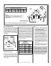
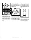
VENT FRAMING -
TOP VENT WITH ONE
90� ELBOW
VENT FRAMING -
REAR VENT WITH
NO ELBOWS
**Framing should be constructed
of 2 x 4 or larger lumber.
Inches (millimeters)
E
(130)
5-1/8
1/2
(130)
7
(308)
(178)
E is the required framing depth dimension when the
finish material (drywall) thickness is 1/2 in. (13mm).
A
**Framing With Square Horizontal Termination SV4.5HT-2
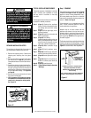
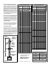
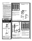
Vertical Venting Through the Ceiling:
Frame ceiling opening - Use a plumb line from
the ceiling above the appliance to locate center
of the vertical run. Cut and/or frame an opening,
10-1/2" x 10-1/2" (267 mm x 267 mm) inside
dimensions, about this center mark (see Figure
20 on Page 14).