


NOTE: DIAGRAMS & ILLUSTRATIONS ARE NOT TO SCALE.
16
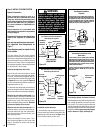
If the vent system extends more than 5 feet
(1.5 meters) above the roof flashing, stabilizers
may be necessary. Additional screws may be
used at section joints for added stability. Guide
wires may be attached to the joint for additional
support on multiple joint configurations.
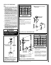
Align the termination over the end of the pre-
viously installed section, adjusting the radial
alignment until the four locking dimples of
the termination are aligned with the inlets of
the four incline channels of the last vent sec-
tion. Push the termination down until it fully
engages, then twist the termination clockwise
running the dimples down and along the incline
channels until they are seated at the end of the
channels.
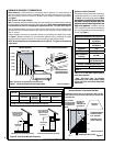
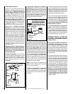
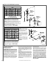
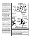
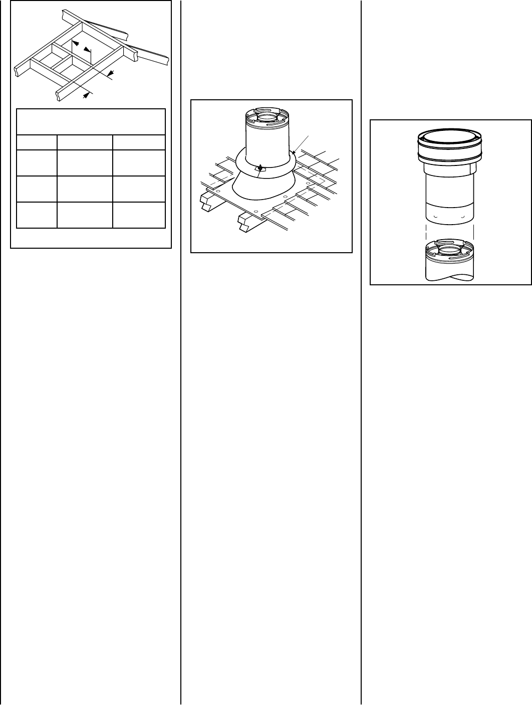
I. Install the roof flashing - Extend the vent
sections through the roof structure. Install the
roof flashing over the vent section and posi-
tion such that the vent column rises vertically
(use carpenters level) (Figure 27). Nail along
perimeter to secure flashing or adjust roofing
to overlap the flashing edges at top and sides
only and trim where necessary. Seal the top
and both sides of the flashing with waterproof
caulking.
Figure 27
Storm
Collar
Figure 28
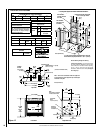
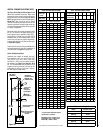
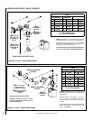
Framing Dimensions for Roof
Inches (millimeters)
Pitch C D
0/12 10-1/2 in.
(267 mm)
10-1/2 in.
(267 mm)
6/12 10-1/2 in.
(267 mm)
12 in.
(305 mm)
12/12 10-1/2 in.
(267 mm)
17 3/4 in.
(451 mm)
C
D
Figure 26- Roof Framing
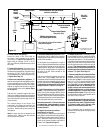
J. Install the storm collar - Install the storm
collar, supplied with the flashing, over the
vent/flashing joint. See Figure 27. Loosen the
storm collar screw. Slide collar down until it
meets the top of the flashing. Tighten the ad-
justing screw. Apply non-combustible caulking
or mastic around the circumference of the joint
to provide a water tight seal.
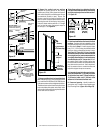
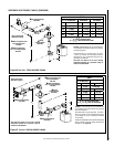
K. Install the vertical termination - The final
step involves installation of the SV4.5CGV-1
Vertical Termination. Extend the vent sections
to the height as shown in the "Vertical vent ter-
mination section" on Page 6. The SV4.5CGV-1
Vertical Termination (Figure 28) can be installed
in the exact same fashion as any other Secure
Vent section.
Flashing