


ULTRA HIGH EFFICIENCY POWER VENT/POWER DIRECT VENT - SERVICE MANUAL
Technical Literature Department 52 of 52 Ashland City, TN © 2008
Servicing should only be performed by a Qualified Service Agent
FAULT MESSAGES (CONT)
DISPLAYED MESSAGE
CONDITION/INDICATES
CHECK/REPAIR
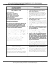
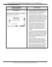
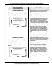
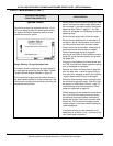
“Gas Valve Failure”
The control system has not detected any current
through the gas valve after it has been energized.
• Turn off power - check all wiring and connectors
between the CCB’s J6 Socket (page 35) pins 2
& 15 and the Gas Valve’s solenoid coil. Repair/
replace anything worn or damaged as neces-
sary.
• Perform close visual inspection of the pins
inside the CCB J6 plug and socket - ensure
plugs and sockets are mating properly and pro-
viding good contact. Repair/replace anything
worn or damaged as necessary.
• Turn off power - disconnect the Gas Valve wir-
ing plug on top of the Gas Valve solenoid coil.
Check Gas Valve solenoid coil resistance with
an ohm meter at the solenoid coil terminals.
Normal resistance is approximately 7 million
ohms. If the Gas Valve solenoid coil is an open
circuit - replace the Gas Valve.
• Check for 24 VAC at CCB’s J6 Socket pins 2 &
15 during the Ignition Activation operating state
(the Gas Valve status icon will be visible on the
UIM display during this period.
• Call the technical support phone number shown
on the water heater labeling for further assis-
tance if the problem has not been corrected
after performing the procedures outlined here.
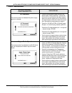
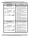
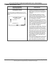
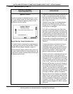
“Communication Failure”
Loss of communication between the CCB and the
UIM.
• Turn off power - check the communication cable
connections between the J2 Socket on the UIM
circuit board (page 27) and the CCB J16 Port
(page 35).
• Try a new communication cable (standard cate-
gory V network cable) between the CCB and the
UIM.
• Call the technical support phone number shown
on the water heater labeling for further assis-
tance if the problem has not been corrected
after performing the procedures outlined here.