


ULTRA HIGH EFFICIENCY POWER VENT/POWER DIRECT VENT - SERVICE MANUAL
Technical Literature Department 10 of 52 Ashland City, TN © 2008
Servicing should only be performed by a Qualified Service Agent
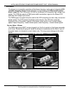
BLOWER
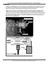
The blower is an assembly consisting of the blower housing, motor and an integrated VFD
(variable frequency drive). Blower operation is controlled by the CCB (central control
board - page 35). The CCB sends 120 VAC to the Blower/VFD assembly high voltage 3 pin
socket. The CCB also sends a PWM (pulse width modulation) signal to the Blower/VFD
assembly low voltage 5 pin socket.
The PWM signal is a digital instruction sent to the VFD instructing it to start, stop, and control
blower speed. The VFD powers the blower motor directly. The VFD also varies the
frequency (Hz) of the power it sends to the blower motor which in turn controls blower
speed. Higher frequency = faster blower speed, lower frequency = slower blower speed.
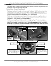
Service Notes - Blower
The PWM signal plug MUST remain plugged in to the 5 pin socket on the blower assembly
at all times. Removing this plug will cause the blower to accelerate and the Btu/hr input of
the water heater to increase to a much higher rate. This may cause damage to the water
heater.
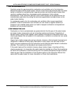
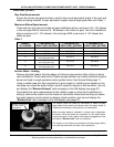
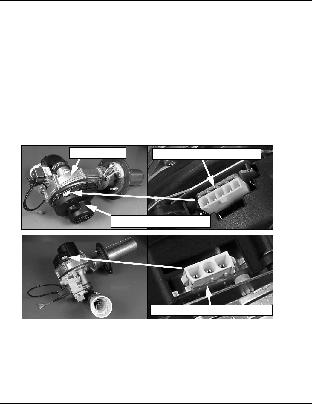
Blower Motor / VFD Assembly
Blower Housing
High Voltage 120 VAC 3 Pin Socket
Low Voltage PWM 5 Pin Socket