


ULTRA HIGH EFFICIENCY POWER VENT/POWER DIRECT VENT - SERVICE MANUAL
Technical Literature Department 22 of 52 Ashland City, TN © 2008
Servicing should only be performed by a Qualified Service Agent
AIR PRESSURE SWITCH TESTING (CONT)
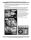
Pressure Test
The Pressure Test is necessary when the air pressure switch in question has passed the
Normal State Test but failed the Operational State Test (see page 21). This test requires a
digital manometer (see Tool Requirements page 3 and the images on page 23).
Before performing this test examine the sensing tube connections on the water heater’s
sensing ports and on the pressure switch (see page 19). Check for wear, leaks, kinks, or any
kind of debris or condensate in the sensing tubes, repair/replace as necessary.
To determine if an air pressure switch is operating properly you must know the “pressure
activation” point for the switch and whether it activates on a rise or a fall in pressure. This
information is provided in Table 3 below.
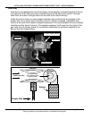
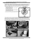
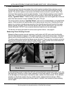
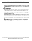
Procedure: Disconnect the pressure sensing tube from the sensing port on the switch being
tested, leave the other end connected. Connect a digital manometer to the sensing tube.
Turn the power on and start a call for heat. When the blower comes up to full speed, record
the pressure reading. Repeat this at all three air pressure switches as necessary. Compare
the pressure readings taken to the activation pressures in Table 3 below. See page 23.
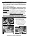
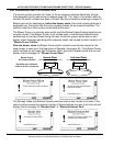
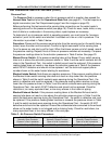
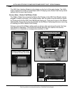
Blower Prover Switch: If the pressure reading taken at the Blower Prover switch sensing
tube is at or above the activation pressure shown in Table 3 and the switch contacts did not
close in the Operational Test - the switch is defective and must be replaced. If the pressure
reading taken does not reach or rise above the activation pressure in Table 3 the pressure
switch IS NOT defective and should not be replaced - call the technical support phone
number shown on the water heater labeling for assistance.
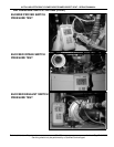
Blocked Intake Switch: Note these are negative pressures. If the pressure reading taken at
the Blocked Intake switch sensing tube does not reach or drop lower than the pressure
shown in Table 3 and the switch contacts were opening during the Operational Test - the
switch is defective and must be replaced. If the pressure reading taken reaches or drops
lower than the pressure shown in Table 3 and the switch contacts were opening during the
Operational Test - the switch IS NOT defective and should not be replaced. Check for
restrictions, too many equivalent feet, or too many elbows in the intake air piping.
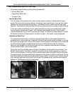
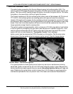
Blocked Exhaust Switch: If the pressure reading taken at the Blocked Exhaust switch
sensing tube does not reach or rise above the activation pressure given in Table 3 and the
switch contacts were opening during the Operational Test - the switch is defective and must
be replaced. If the pressure reading taken reaches or exceeds the pressure shown in Table
3 and the switch contacts were opening during the Operational Test - the switch IS NOT
defective and should not be replaced. Ensure the condensate tube connected to the exhaust
elbow on the water heater is not clogged and is draining freely. Check for restrictions, too
many equivalent feet, or too many elbows in the vent pipe.
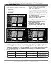
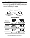
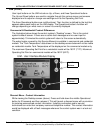
Table 3 - Air Pressure Switch Parameters
BLOWER PROVER
Normally Open Contacts
Close on a rise in pressure
BLOCKED INTAKE
Normally Closed Contacts
Open on a fall in pressure
BLOCKED EXHAUST
Normally Closed Contacts
Open on a rise in pressure
+1.00” W.C.(± 0.05” W.C) -2.00” W.C. (± 0.05” W.C) +2.00” W.C. (+0.05” W.C)