


ULTRA HIGH EFFICIENCY POWER VENT/POWER DIRECT VENT - SERVICE MANUAL
Technical Literature Department 20 of 52 Ashland City, TN © 2008
Servicing should only be performed by a Qualified Service Agent
AIR PRESSURE SWITCH OPERATION
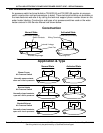
The control system monitors the “state” of the air pressure switches individually through
three separate circuits (see wiring on diagram page 39). The “state” of the switch refers to
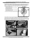
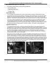
whether the switch contacts are open or closed. See the construction drawings on page 18.
Before each call for heat begins, before the blower starts, the control system performs a
diagnostic test. During this test the control system checks the air pressure switches. The
switches must be in their correct normal state at this point.
The Blower Prover is a normally open switch and the Blocked Intake/Exhaust switches are
normally closed. If the Blower Prover is not verified open or the Blocked Intake/Exhaust
switches are not verified closed during this test; the control system would lock out and
display a fault message indicating which pressure switch had caused the fault condition. IE:
“Blower Prover Failure.”
After the blower starts the Blower Prover switch contacts must activate (close) for the
water heater to continue in the Sequence of Operation (see page 40). If the Blower Prover
switch contacts do not close after the blower starts, the control system would lock out and
display a fault message; IE: “Blower Prover Open.”
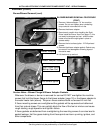
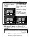
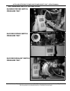
The Blocked Intake and Blocked Exhaust switches must remain closed at all times. If the
control system senses the contacts of either of these switches are open it will lock out and
display a fault message; IE “Blocked Inlet” or “Blocked Exhaust Vent”
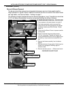
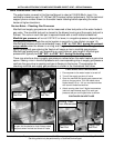
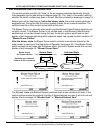
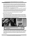
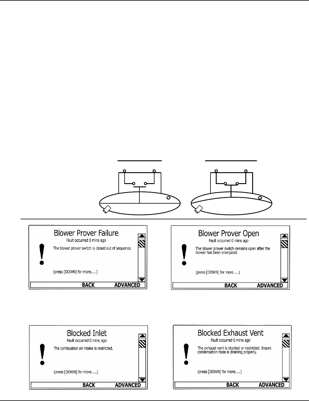
Normal State Activated State
Blower Prover
Air Pressure Switch
Normally open contacts,
close on a rise in pressure.
(contacts open - before blower starts)
(contacts closed - after blower starts)