


ULTRA HIGH EFFICIENCY POWER VENT/POWER DIRECT VENT - SERVICE MANUAL
Technical Literature Department 50 of 52 Ashland City, TN © 2008
Servicing should only be performed by a Qualified Service Agent
FAULT MESSAGES (CONT)
DISPLAYED MESSAGE
CONDITION/INDICATES
CHECK/REPAIR
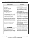
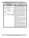
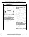
“Ignition Failure”
The control system has detected less than 1.0 µA
(DC micro amps) through the flame sensor during
the Ignition Verification operating state on three
consecutive trials for ignition.
Rough Starting - Rough Operation Note:
If the water heater is experiencing rough operation
or rough starting review the Service Notes - Blower
Flange & Blower Adapter Gaskets on page 13.
Call the technical support phone number shown on
the water heater labeling for further assistance if the
problem has not been corrected after performing the
procedures outlined here.
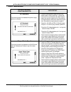
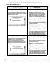
• Visually check for burner flame through the view
port on the top of the water heater (see illustra-
tions on page 11) during the Ignition Verification
operating state (Table 5 - page 31) - the Gas
Valve icon will appear on UIM display during this
operating state.
• Ensure the gas supply shut off valve is open.
• Ensure there is adequate air for combustion &
ventilation. See air requirements in the Instruc-
tion Manual that came with the water heater.
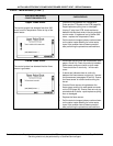
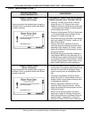
• Ensure the burner is grounded - see electrical
requirements and service notes on page 8.
• Ensure flame sensor wiring is plugged in
securely at the CCB’s J4 male spade connector
(page 35) and at the flame sensor wiring termi-
nal (page 24).
• Check all wiring between the flame sensor and
the CCB J4 connection. Repair/replace anything
worn or damaged as necessary.
• Remove and clean the flame sensor (page 24)
with fine steel wool - check for signs of exces-
sive wear, bent, damage, cracks in the insulator
- replace flame sensor if worn or damaged.
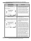
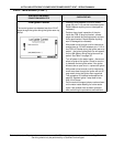
• Check for flame sensing current during the Igni-
tion Verification operating state - Gas Valve icon
will appear on UIM display (Table 5 - page 31).
Flame sensing current test procedure is illus-
trated and explained on page 24.
If flame sensing current measured is well above
the 1.0 µA (DC micro amps) minimum during
this test and the control system continues to
declare the Ignition Failure fault condition after
three trials - call the technical support phone
number shown on the water heater labeling for
further assistance.
If the flame sensing current measured is not
established or is below 1.0 µA - continue to the
next check/repair procedure.