


ULTRA HIGH EFFICIENCY POWER VENT/POWER DIRECT VENT - SERVICE MANUAL
Technical Literature Department 26 of 52 Ashland City, TN © 2008
Servicing should only be performed by a Qualified Service Agent
CONTROL SYSTEM
INTRODUCTION
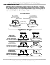
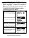
This portion of the service manual will cover the control system. The control system includes
several components: a UIM (User Interface Module), a CCB (Central Control Board), and an
Overlay/Button Pad. More information on these components will be given in the pages that
follow.
Control System Features
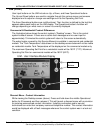
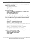
Advanced Diagnostics: Plain english text based diagnostic information (fault messages)
on board to help equipment owners accurately describe the reason for a given lock out
condition and service technicians quickly and accurately service the water heater.
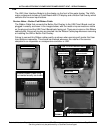
Fault History Screen: Will retain a 9 event history of fault messages with a time stamp.
This will help diagnose load and/or environmental conditions that may be contributing to a
problem with operation or a lock-out.
Fault Occurrence Screen: Will keep a running total of how many times each lock out/fault
condition has occurred since the water heater was first installed. This is valuable information
for a service technician when trying to determine root causes for service problems.
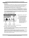
Help Screens: Text based operational information to help the user understand how to
change settings, navigate the menu screens and what the various icons and displayed items
mean.
EMI / RFI Filtering: Built into all control system circuit boards. (EMI = Electro Magnetic
Interference, RFI = Radio Frequency Interference) Helps prevent or eliminate erratic
operation caused by EMI/RFI.