


Technical Literature Department 13 of 52 Ashland City, TN © 2008
Servicing should only be performed by a Qualified Service Agent
ULTRA HIGH EFFICIENCY POWER VENT/POWER DIRECT VENT - SERVICE MANUAL
BURNER (CONT)
Burner/Blower Removal (cont)
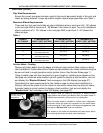
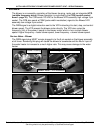
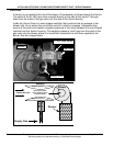
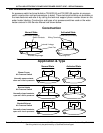
Service Notes - Blower Flange & Blower Adapter Gaskets.
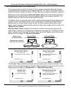
Whenever the blower or burner is removed for service DO NOT overtighten the machine
screws that hold the blower flange to the blower adapter (page 12) or the blower adapter to
the water heater tank (above). Torque on these screws should not exceed 40 inch lbs.
If these mounting screws are overtightened the gaskets will be squeezed and deformed
from their natural shape. This can partially block the flow of the fuel air mixture and cause
rough starting, rough operation and ignition failure.
If these gaskets are deformed from overtightening the mounting screws it can also lead to
gasket leakage. Hot flue gases leaking from these points can burn up wiring, igniters, and
other components.
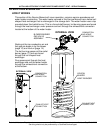
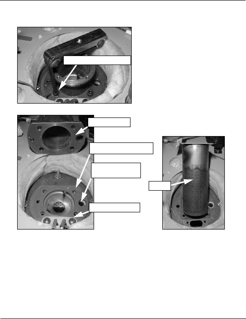
Blower Adapter
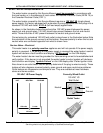
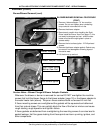
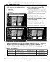
BLOWER/BURNER REMOVAL PROCEDURE
(CONT)
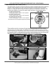
9 Remove 4 blower adapter 1/4” hex machine
screws. Do not over tighten when reinstalling -
torque should not exceed 40 inch lbs.
10 Remove the blower adapter.
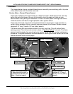
11 Be extremely careful when handling the Sight
Glass inside the Burner View Port (page 11) this
can easily be dropped and lost - and the water
heater must have the sight glass in place to
operate safely.
12 Remove the hot surface igniter - 2 Phillips head
screws.
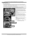
13 Remove the blower adapter gasket. Gasket may
be reused if not damaged or showing signs of
excessive wear.
14 Lift the burner up and out.
1/4” Hex Machine Screws
Hot Surface Igniter
Burner
Blower Adapter Gasket
Sight Glass inside
Burner View Port