


Technical Literature Department 49 of 52 Ashland City, TN © 2008
Servicing should only be performed by a Qualified Service Agent
ULTRA HIGH EFFICIENCY POWER VENT/POWER DIRECT VENT - SERVICE MANUAL
FAULT MESSAGES (CONT)
DISPLAYED MESSAGE
CONDITION/INDICATES
CHECK/REPAIR
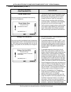
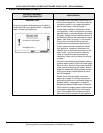
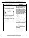
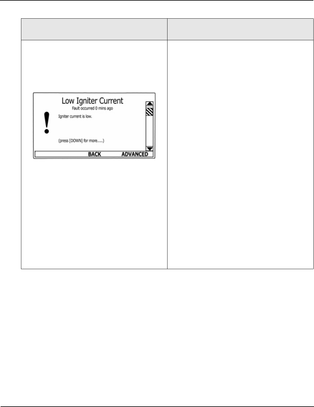
“Low Igniter Current”
The control system has detected less than 2.0 AC
amps through the igniter during the igniter warm up
period.
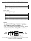
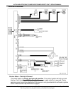
• Check all wiring between CCB’s J5 Socket
(page 35) pins 1 & 2 and the hot surface igniter.
Repair/replace anything worn or damaged as
necessary.
• Perform close visual inspection of the pins
inside the CCB J5 plug and socket - ensure
plugs and sockets are mating properly and pro-
viding good contact. Repair/replace anything
worn or damaged as necessary.
• With power turned on and a call for heat active -
ensure there is 120 VAC between pins 1 & 2 of
the CCB’s J5 Socket during the igniter warm up
period. - the igniter lighting bolt icon will appear
on the UIM display during the igniter warm up
period. See Table 4 on page 30.
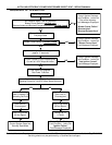
• Turn off power to the water heater - disconnect
wires to igniter at the igniter. Check for continu-
ity between the two igniter wires. If the igniter
shows to be an open circuit - replace the igniter.
• With power turned on and a call for heat active -
check amp draw through the igniter with an AC
amp meter during the igniter warm up period.
This procedure is illustrated and explained on
page 25. Replace igniter if amp draw is less
than 3.0 AC amps.
• Call the technical support phone number shown
on the water heater labeling for further assis-
tance if the problem has not been corrected
after performing the procedures outlined here.