


ULTRA HIGH EFFICIENCY POWER VENT/POWER DIRECT VENT - SERVICE MANUAL
Technical Literature Department 16 of 52 Ashland City, TN © 2008
Servicing should only be performed by a Qualified Service Agent
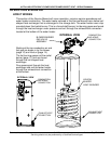
GAS PRESSURE TESTING
The water heater covered in this Service Manual is rated at 100,000 Btu/hr input. It is
certified for elevations up to 10,100 feet (3079 meters) without adjustment. Call the technical
support phone number shown on the water heater labeling before operating the water
heater at higher elevations.
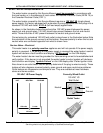
Service Notes - Checking Gas Pressures
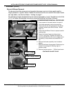
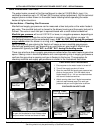
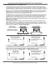
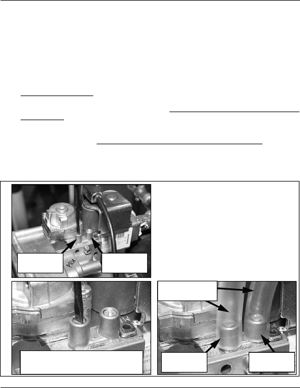
Manifold and supply gas pressure can be measured at two test ports on the water heater’s
gas valve. The manifold test port is closest to the blower housing and the supply test port is
furthest. The valve in each test port is opened/closed with a small slotted screwdriver.
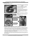
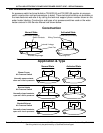
Manifold gas pressure will run at 0.00” W.C. or lower, in a negative pressure, depending on
the operating state or mode the control system is currently in (see Venturi on page 14).
Manifold gas pressure will be considerably lower, -6.50” to -7.50” W.C. during the pre/post
purge modes when the blower is running and the gas valve is closed. When the gas valve
opens (energized) gas entering the Venturi will cause a rise in manifold gas pressure.
Manifold gas pressure will vary depending on vent/intake air pipe lengths. Manifold gas
pressure will typically be 0.00” W.C. to +0.05” W.C. during the heating mode.
There may also be a drop in supply gas pressure noticed when the water heater’s gas valve
opens. Seeing a rise in manifold pressure and a corresponding drop in supply gas pressure
confirms the gas valve is opening and gas is flowing to the burner. The procedure for
checking manifold and supply gas pressures is shown in the illustrations that follow.
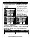
CHECKING GAS PRESSURES
1 Ensure power to the water heater is turned off.
2 Turn off the supply gas shut off valve.
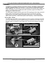
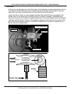
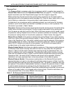
3 Open the manifold and supply gas pressure test
ports on the gas valve. Turn the needle valve
slotted heads 1/2 to 1 full turn counterclockwise
with a small slotted screwdriver.
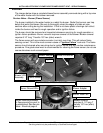
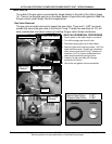
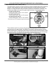
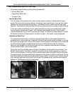
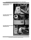
4 Attach sensing tube from 2 digital manometers
(see tool requirements page 3) to each gas
pressure test port on the gas valve as shown.
CONTINUED ON NEXT PAGE
Supply Gas
Test Port
Manifold Gas
Test Port
Manifold Gas
Test Port
Supply Gas
Test Port
Turn test port needle valves counter-clockwise
to open and clockwise to close. Always close
test ports when finished and check for leaks
Sensing Tubes
From Manometers