


User Manual Chapter 1 Introduction 9
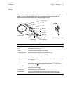
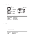
Probe
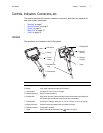
The probe is the flexible eye of the system.
Various probe models are available with insertion tubes of different diameters and different
lengths. You can change probes quickly. You can also travel lighter by carrying one
system and a spare probe rather than a complete spare system.
Item Description
A. Strain relief Allows the insertion tube to twist up to 180 degrees in either direction.
B. Clip Holds probe end when not in use.
C. Latch C-shaped piece that locks the probe in the handset.
D. Electrical connector Enables communication between base unit, handset, and probe.
E. Fiberoptic connector Couples light from the handset into the insertion tube.
F. Motor shaft connectors For controlling the articulation cables.
G. Optical tip Removable part containing unique precision optics. For a list of available tips, see “Optical
Tips” on page 141.
H. Temperature sensor For 6.1 mm probes only. Displays a warning symbol and beeps when temperature at the
probe tip approaches or exceeds operating temperature limits. For an example of the
warning symbol, press , and select Setup > Temp Sensor.
I. Camera head Made of titanium for superior protection. Contains a high-resolution, durable camera that
provides clear, true-color images.
J. Bending neck The articulating section of the insertion tube.
K. Insertion tube A woven tube of tungsten wire that protects the electrical conductors and the light-
transmission fibers. Conducts light to the inspection area, and returns digital images.
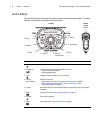
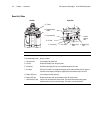
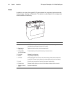
D. Electrical
connector
C. Latch
Probe inserted into handset
G. Optical tip
K. Insertion tube
J. Bending neck
F. Motor shaft
connectors
A. Strain relief
E. Fiberoptic
connector
I. Camera head
B. Clip
H. Temperature
sensor