


User Manual Chapter 1 Introduction 7
Controls, Indicators, Connectors, etc.
This section describes the controls, indicators, connectors, and other key elements for
each main system component:
• “Handset” on page 7
• “Control Buttons” on page 8
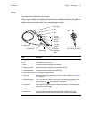
• “Probe” on page 9
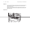
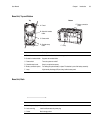
• “Base Unit” on page 10
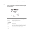
• “Case” on page 14
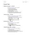
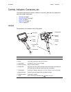
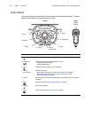
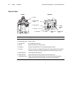
Handset
The handset is your interface to the XLG3 system.
Item Description
A. Microphone Lets you record voice comments for video or still images.
B. Display Large, bright, high-resolution wide-VGA LCD screen.
C. Control buttons For details, see “Control Buttons” on page 8.
D. Shoulder-strap loops Strap is an optional accessory.
E. Handset cable Plugs into the base unit. Powers the handset, enables communication with the base unit,
and conducts light via a fiberoptic bundle from the lamp to the handset.
F. Flashlight LEDs Provide light for reading or writing. See “To Turn the Flashlight On and Off” on page 29.
G. Electrical connector Enables communication between base unit, handset, and probe.
H. Fiberoptic connector Couples light to the probe.
I. Trigger Same functions as the freeze/enter button (item B. on page 8).
GE
Inspection Technologi
es
Everest XLG3
B. Display
C. Control
buttons
G. Electrical
connector
I. Trigger
F. Flashlight LEDs
E. Handset cable
A. Microphone
H. Fiberoptic
connector
D. Shoulder-strap
loops