


98 Chapter 7 Measuring Features and Defects GE Inspection Technologies XLG3 VideoProbe System
Types of Stereo Measurement
This table specifically addresses cursor placement for each type of stereo measurement.
For the complete procedure, see “To Take a Stereo Measurement” on page 96.
Type
Example —
“Matching Cursors” on Right Image Description
Cursor Placement
On Left Image
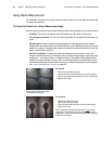
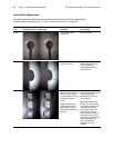
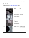
Length A linear (point-to-point)
measurement.
Place both cursors.
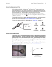
Point to Line The perpendicular distance
from a point to a line.
Place the first two cursors to
define a reference line. Place
the third cursor at the
perpendicular distance you
want to measure.
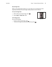
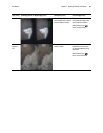
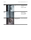
Depth The perpendicular distance
between a surface and a point
above or below it. Used to
evaluate changes due to wear,
misalignment, and other
causes.
Negative measurements
indicate that the point lies
below the plane. Positive
measurements indicate that it
lies above.
Place the first three cursors to
define a reference plane. Place
the fourth cursor at the
perpendicular distance you
want to measure.
Note: Depth measurements
taken at a low accuracy index
are particularly sensitive to the
matching cursor’s position.
If the accuracy index is low,
increase it by bringing the
probe tip closer. If you cannot
increase the accuracy index,
place cursors so that they yield
high match strengths, and
verify your accuracy as
described in Step 8 on
page 96.