


88
1-1 1-2
2-1 2-2 2-9
1-3 1-13
2
9
2
1
ON
3
ON
1
2
3
ON
1
2
3
ON
1
2
3
ON
1
2
2
ON
1
3
1
3
1
ON
3
2
ON
1
2
2
ON
1
3
3
2
1
ON
ON
OFF
ON
OFF
ON
OFF
ON
OFF
ON
OFF
ON
OFF
ON
OFF
ON
OFF
ON
OFF
ON
OFF
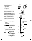
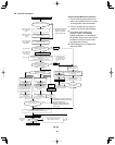
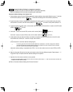
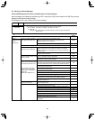
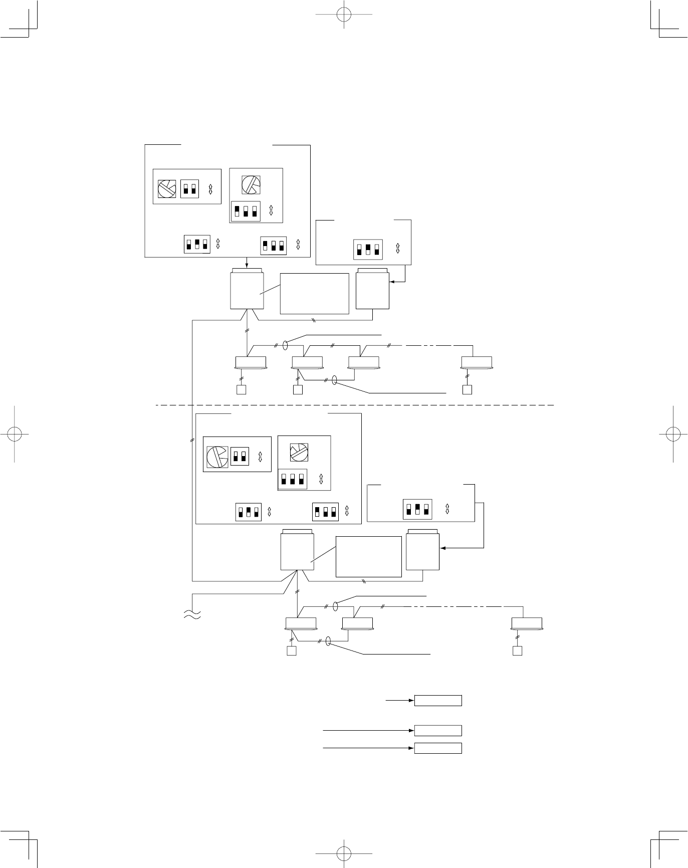
Automatic address setting in Heating mode
Automatic address setting in Cooling mode
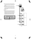
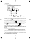
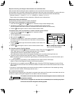
* When multiple outdoor main units exist, remove the socket that
is used to short-circuit the terminal plug (CN003) from all
outdoor main unit PCBs except for 1.
Alternatively, move the sockets to the “OPEN” side.
Leave the socket that
is used to short-circuit
the terminal plug.
(CN003)
To other system
link wiring
• Indoor and outdoor unit power can be turned ON for each system separately.
Case 2
Case 1
Case 3
Make settings as appropriate for the cases listed below.
(Refer to the instructions on the following pages.)
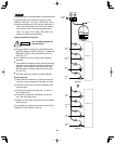
Leave the socket
that is used to open
circuit the terminal
plug (CN003).
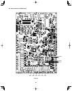
(S006)
(S007)
(S005)
(S004)
(S003)(S002)
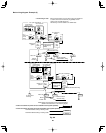
• If link wiring is used
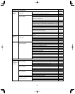
No. 1 (main unit) settings
No. 2 (sub unit)
settings
Unit
No. 2
(Sub)
Unit
No. 1
(Main)
Outdoor unit
system 1
Unit
No. 2
(Sub)
Unit
No. 1
(Main)
Outdoor unit
Indoor unit
Remote
controller
Indoor unit
Remote
controller
Outdoor main/sub control wiring
Inter-unit control wiring
Inter-unit control wiring
Remote controller
communication wiring
Remote controller
cross-over wiring
(S007)
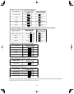
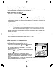
No. 2 (sub unit) settings
(S007)
(S006)
(S007)
(S005)
(S004)
(S003)(S002)
No. 1 (main unit) settings
System address
(system 1 setting)
System address
(system 2 setting)
No. of indoor units
(13 units setting)
No. of indoor units
(9 units setting)
No. of
outdoor
units (2 units
setting)
No. of
outdoor units
(2 units
setting)
Unit
number
setting
(unit No. 1)
Unit
number
setting
(unit No. 2)
Unit
number
setting
(unit No. 2)
Unit
number
setting
(unit No. 1)
system 2
• Indoor and outdoor unit power cannot be turned ON for each system separately.
Basic wiring diagram: Example (2)
Fig. 8-6