


70
●
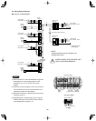
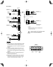
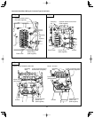
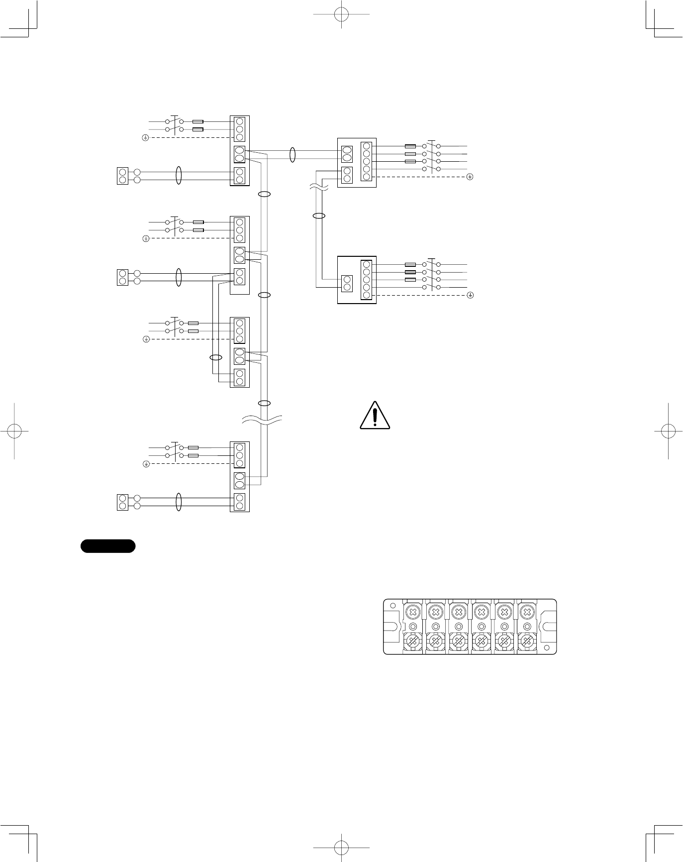
For XM Type
U2
U1
3
1
2
1
2
2
1
U2
U1
4
3
3
4
5
2
1
2
1
U2
U1
3
1
2
1
2
U2
U1
3
1
2
1
2
U2
U1
3
1
2
1
2
2
1
2
1
2
1
B
C
A
L1
L2
L3
N
L
N
L
N
L
N
L
N
2
1
2
1
4
3
3
4
5
L1
L2
L3
N
A
D
B
B
A
A
*
*
*
*
*
*
* Disconnect switch
(
Field Supply)
Power supply
208/230V, 1ø, ~60Hz
Power supply
208/230V, 3ø, ~60Hz
Power supply
208/230V, 3ø, ~60Hz
Remote
controller
Indoor unit
(No. 1)
Indoor unit
(No. 2)
Indoor unit
(No. 3)
Indoor unit
(No. n)
Outdoor unit
INV unit
Outdoor unit
INV unit
Inter-outdoor-unit control wiring
WHT
BLK
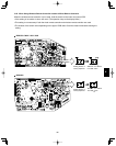
Group control:
Power supply
208/230V, 1ø, ~60Hz
Power supply
208/230V, 1ø, ~60Hz
Power supply
208/230V, 1ø, ~60Hz
Remote
controller
Remote
controller
WHT
BLK
WHT
BLK
Ground
Ground
Ground
Ground
Ground
Ground
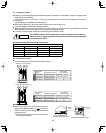
NOTE
(1) Refer to Section 5-2. “Recommended Wire Length
and Wire Diameter for Power Supply System” for
the explanation of “A,” “B,” “C,” and “D,” in the above
diagram.
(2) The basic connection diagram of the indoor unit
shows the 6P (XM type) terminal board, so the ter-
minal boards in your equipment may differ from the
diagram.
(3) Refrigerant Circuit (R.C.) address should be set
before turning the power on.
(4) Regarding R.C. address setting, refer to page 87.
Auto address setting can be executed by remote
controller automatically. Refer to page 87 – 91.
L N U1 U2 R1 R2
XM Type
6P terminal board
POWER
SUPPLY
UNIT CONTROL
LINE
REMOTE
CONTROL
LINE
ALWAYS COMPLY WITH NATIONAL AND
LOCAL CODE REQUIREMENTS.
*
NOTE:
Disconnect Switch may be needed by the
National/Local code.